seat Workshop Repair Guides

SEAT Workshop Service and Repair Manuals

Gear drive mechanism: removing and installing|Installation > < Gear drive mechanism: removing and installing
Removing
Removing
–  With the ignition switched off disconnect battery earth strap.
  Note!
For vehicles fitted with a coded radio, first check the anti-theft code.
–  Release the frame cover.
   
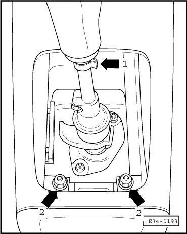
–  Turn the casing over and remove the gear stick knob, loosening the clip -arrow 1-.
–  Remove the bolts that secure the central console to the protective cover -arrow 2-.
–  Remove the insulation tray: → General Body Repairs, exterior; Rep. Gr.50.
–  Remove the front exhaust pipe from the intermediate flange of the exhaust system: → 4 cyl. diesel engine, mechanical; Rep. Gr.26.
  E34-0198
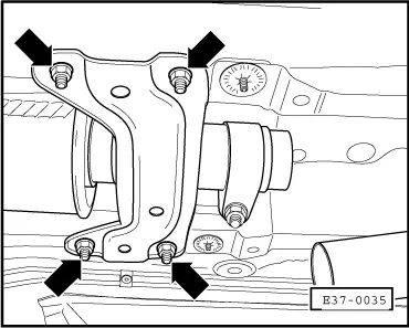
–  Remove the front beam -arrows-. located under the exhaust system.
–  Support the exhaust system from below, between the front and the rear beam.
  E37-0035
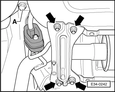
–  Remove the rear beam -arrows- and unscrew the support with the elastic supporting ring from its connection to the bodywork -A-.
–  Lower the exhaust assembly until it is possible to remove the heat shields.
–  Remove the front and rear heat shields.
–  Lever and release the long selector rod from the selector lever. To do this first open the clip.
–  Remove the control rod pin (with counterweight) and separate it from the intermediate lever.
  E34-0242
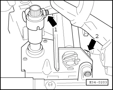
–  Unscrew the clamp for the control rod/selector lever assembly clamp -arrow 1-. The selector lever should slide freely on the control rod.
–  Remove the selector lever. To do this, first turn the selector lever anti-clockwise to release it from the coupling shaft socket, and move it foreward to remove from the control rod.
–  Remove the front bolt -arrow 2- that secures the coupling shaft bracket to the steering box.
  E34-0203
–  Remove the rear bolts that secure the coupling shaft to the steering box -arrows-.
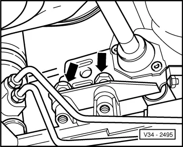
–  Remove the coupling shaft assembly from below. To do this, push the control rod back to its limit and to the right; move the coupling shaft assembly out.
  V34-2495
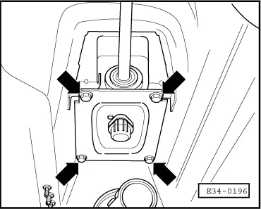
–  Unbolt the protective cover from the bodywork -arrows-.
  E34-0196
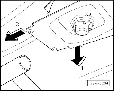
–  Tilt the protective cover downwards with the control rod -arrow 1-, move it towards the engine -arrow 2-, and remove.
  Note!
On lowering the protective cover, take note of the central console spacers.
  E34-0204

Gear drive mechanism: removing and installing|Installation > < Gear drive mechanism: removing and installing