
Leon Mk1
 Note!
Note!
|

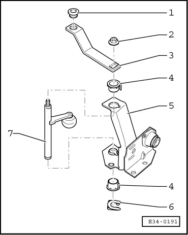
| 1 - | Securing pin |
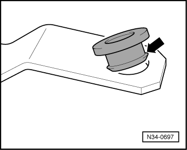
| 2 - | Bearing bush |
| q | Fit → Fig. |
| 3 - | Selector rod (short) |
| q | Removal: open the tie with a screwdriver and separate the ball joints by levering with a screwdriver |
| q | Install: fit in the ball joints with pliers and close the plastic tie |
| 4 - | Hexagon bolt |
| q | To secure the coupling lever to the console |
| 5 - | Control rod |
| q | With counterweight |
| 6 - | Hexagon combi bolt |
| q | 20 Nm |
| q | Self-locking |
| q | To secure the clip to the control rod |
| 7 - | Clip |
| q | Assembly position: the notch on the clip should coincide with the projection guide on the gear stick |
| 8 - | Hexagon bolt |
| q | To secure the clip to the control rod |
| 9 - | Sealing washer |
| q | Renew if damaged |
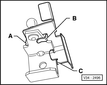
| 10 - | Selector lever |
| q | With heat shield. Cannot be replaced separately |
| q | Assembly position of the heat shield → Fig. |
| 11 - | Control rod |
| q | Remove it together with the gear stick, from the protective cover → Fig. |
| 12 - | Hexagon bolt |
| q | 25 Nm |
| q | Securing the support block to the steering box |
| 13 - | Support block |
| q | Bearing bush for control rod. Cannot be replaced separately |
| q | Dismounting and installation of the coupling shaft → Fig. |
| q | Coupling shaft bush: Renew if damaged |
| q | Coupling shaft bush: Fit → Fig. |
| 14 - | Selector rod (long) |
| q | Removal: open the tie with a screwdriver and separate the ball joints by levering with a screwdriver |
| q | Install: fit in the ball joints with pliers and close the plastic tie |
| 15 - | Return lever |
| 16 - | Bearing bush |
| q | Renew if damaged |
| 17 - | Gear stick console |
| q | It will not be necessary to remove it on removing the coupling lever |
| 18 - | Hexagon nut |
| q | 15 Nm |
| q | Self-locking |
| q | To secure the coupling lever to the console |
| 19 - | Hexagon nut |
| q | 25 Nm |
| q | Self-locking |
| q | To secure the selector rod to the gearbox |
| 20 - | Selector rod |
| q | Only fits to the selector shaft in one position |
| 21 - | Gear change |
|
|
|
|