seat Workshop Repair Guides

SEAT Workshop Service and Repair Manuals

Exhaust system > < Components and functions: testing
Test process
Test process
–  Attach the -V.A.G. 1551- (-V.A.G. 1552-) and, with the corresponding “address code” 01, select the engine electronics control unit. When doing so, the ignition must be on. (Fault reader: connecting and selecting the engine electronics control unit → Vehicle diagnosis, testing and information system VAS 5051.)
   
Reading on the display:
–  Press 0 and 8 for the function “Read measured value block” and confirm the entry with the Q button.
 
Rapid data transmission             HELP
Select function XX                      
Reading on the display:
–  Press 0, 1 and 0 for “Display group number 10” and confirm the entry with the Q button.
 
Read measured value block               
Enter value group number XXX            
– 
–  Test the values shown in fields 2 (altimetric sender -F96-) and 3 (intake manifold pressure sender -G71-) and in the turbocompressor tester -V.A.G. 1397/A- Target value: the pressures must coincide (tolerance of ± 30 mbar)
  Note!
The turbocompressor tester is needed for obtaining an independent comparative value. The turbocompressor tester must be set to measurement range I (absolute pressure). In its place a barometer may also be used.
The value displayed in field 2 differs:
–  Press .
–  Press 0 and 6 for the function “End transmission” and confirm the entry with the Q button.
–  Switch off the ignition.
–  Replace the direct diesel injection system control unit -J248- → Anchor.
If the value displayed in field 3 differs:
–  Press .
–  Press 0 and 6 for the function “End transmission” and confirm the entry with the Q button.
–  Start the engine and select again the function 08 “Read measured value block”.
–  Press 0, 1 and 0 for “Display group number 10” and confirm the entry with the Q button.
–  Detach the connector from the intake manifold pressure sender → Chapter
–  Check the value in display field 3 (intake manifold pressure sender).
 
Read measured value block 10           →
0 mg/stroke  1027 mbar  1013 mbar  0.0 %
– 
–  It should descend continually and then adopt the value of the altimetric sender (display field 2).
If the target value is reached:
–  Replace the intake manifold pressure sender with the temperature sender on the intake manifold.
If the target value is not reached:
–  Press .
–  Press 0 and 6 for the function “End transmission” and confirm the entry with the Q button.
–  Switch off the ignition.
 
Read measured value block 10           →
515 mg/stroke1,009 mbar 1,009 mbar 0.0 %
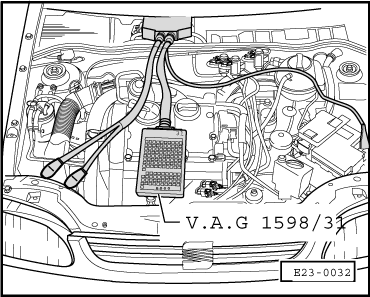
–  Attach the test box -V.A.G. 1598/31- to the wiring harness of the control unit.
  E23-0032
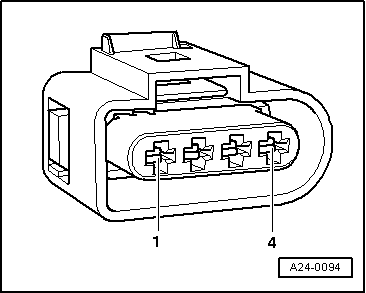
–  Test for open circuits in the wiring between the test box and the connector, following the wiring diagram. Contact 3 + female contact 31 Contact 4 + female contact 71 Wiring resistance: 1.5 Ω max.
–  Also test for short circuits between wires, to vehicle earth and to positive battery. Target value: ∞ Ω
If no fault is found in the wiring:
–  Replace the direct diesel injection system control unit -J248- → Anchor.
  A24-0094

Exhaust system > < Components and functions: testing