seat Workshop Repair Guides

SEAT Workshop Service and Repair Manuals

Camshaft seal: removing and fitting > < Valve guides: verification
Replacing valve shaft seals.
Check the tool and equipment equivalence table according to the applicability between Seat / VW / Audi / Skoda → Chapter
   
Special tools and workshop equipment required
t  Articulated wrench e/c 10 -3220-, see equivalent → Anchor
t  Valve stem seal extractor -3364-, see equivalent → Anchor
t  Tool for inserting seals onto the valve stems -3365-, see equivalent → Anchor
t  Removal / installing device for valve cotters -VAS 5161- with guide plate -VAS 5161/23- and knurled spacer ring -VAS 5161/23-1-, see equivalent → Anchor

Removal:
»Carry out the following work sequence«
–  Remove all glow plugs using U/J extension and socket -3220- → Chapter.
–  Remove camshafts → Chapter.
–  Remove roller rocker arm; Observe the installation position of the roller rocker arm → Item.
–  Place guide plate -VAS 5161/23- onto cylinder head.
   
–  Secure guide plate on intake manifold side using knurled screw -VAS 5161/12- and M6 bolts -1-.
  N15-10525
–  Screw sealing bolt -VAS 5161/10- into the guide plate.
–  Screw adapter -VAS 5161/11- into the respective glow plug thread hand-tight.
  N15-10526
–  Insert punch -VAS 5161/3- into guide plate and use a plastic hammer to knock loose the firmly seated valve cotters.
  N15-10527
–  Screw engaging fork -VAS 5161/5- with snap-in device -VAS 5161/6- into guide plate.
–  Slide knurled spacer ring -VAS 5161/23-1- onto assembly cartridge -VAS 5161/8-.
–  Connect adapter -VAS 5161/11- to compressed air using a commercially available intermediate piece. Leave constantly under pressure.
l  Minimum pressure: 6 bar
–  Attach pressure fork -VAS 5161/2- to snap-in device and push assembly cartridge down.
–  At the same time, turn knurled screw of assembly cartridge clockwise until tips engage in valve cotters.
–  Move knurled screw back and forth slightly to press apart valve cotters and capture them in the assembly cartridge.
–  Remove the pressure prong.
–  Remove the assembly cartridge with a knurled spacer ring, valve head and valve spring.
  N15-10528
–  Pull off valve stem seals using valve stem seal puller -3364-.
  Note
  N15-10529
A plastic sleeve -A- is included with the new valve stem oil seals.
–  Fit plastic sleeve -A- onto valve stem to prevent damage to new valve stem seals -B-.
–  Lightly oil sealing lip of valve stem seal.
–  Push valve stem seal onto plastic sleeve.
–  Carefully press valve stem oil seal onto valve guide using valve stem seal fitting tool -3365-.
–  If necessary, use a plastic head hammer and tap lightly on fitting tool until valve stem seal is fitted to stop.
–  Remove the plastic sleeve again.
–  Insert valve spring and valve plate into cylinder head.
  A15-0282
–  If valve cotters have been removed from assembly cartridge, they need to be put into insertion device -VAS 5161/18- first.
  Note
Larger diameter of valve cotter pins faces upwards.
–  Press assembly cartridge onto insertion device from above and pick up valve cotters.
  A15-0445
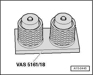
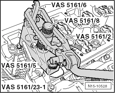
–  Insert installation cartridge -VAS 5161/8- into guide plate again.
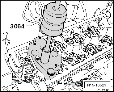
–  Lower the pressure fork and pull towards the knurled screw and at the same time turn towards the left and right. Now the valve cones are inserted.
–  Release pressure fork with knurled screw still in pulled position.
Installation is carried out in the reverse sequence; note the following:
–  Install camshafts → Chapter.
–  Install glow plugs → Chapter.
  Note
t  After installing cam shaft, the engine must not be started for approx. 30 minutes. The hydraulic elements should be allowed to sit in place (if not, the valves may press on the cylinder).
t  After working on the valve gear, turn the engine carefully at least 2 rotations to ensure that none of the valves make contact when the starter is operated.
  N15-10528

Camshaft seal: removing and fitting > < Valve guides: verification