
Leon Mk1
| Valve gear - exploded view |
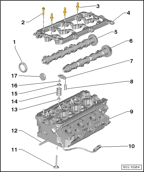
| 1 - | Seal |
| q | Do not additionally oil or grease the oil seal sealing lip. |
| q | Before fitting, use a clean cloth to wipe off oil residue on camshaft journal. |
| q | For fitting, cover the groove in the camshaft cone (for example using sellotape). |
| q | removing and fitting → Chapter |
| 2 - | 10 Nm |
| 3 - | Guide pins |
| q | 10 Nm |
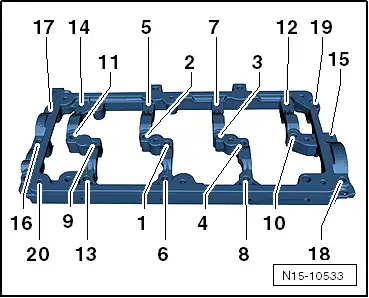
| 4 - | Retaining frame |
| q | Observe sequence when loosening and tightening → Chapter. |
| q | Seal using silicone adhesive sealant -D 176 501 A1-. |
| 5 - | Exhaust camshaft |
| 6 - | Supply camshaft |
| 7 - | Roller rocker arms |
| q | Mark the installation position |
| q | Do not mix them up |
| q | Check roller bearing for ease of movement. |
| q | Oil cam contact surface before installing. |
| 8 - | Hydraulic valve compensation element |
| q | Mark the installation position |
| q | Lubricate contact surfaces before installing. |
| 9 - | Cylinder head |
| q | See note → Chapter |
| q | removing and fitting → Chapter |
| 10 - | Hall sender -G40- connector |
| q | removing and fitting → Chapter |
| 11 - | Valve |
| q | Not to be reworked; only grinding-in permissible |
| q | Mark the installation position |
| q | Valve dimensions → Chapter |
| q | Checking valve guides → Chapter |
| 12 - | Stud |
| 13 - | Valve stem seal |
| 14 - | Valve spring |
| 15 - | Valve plate spring |
| 16 - | Valve cotter |
| 17 - | Sealing cap |
| q | Replace |
|
|
| stage: | Bolts | Tightening torque | ||
| 1. | -1 … 20- | Screw in bolts by hand until they make contact
| ||
| 2. | -1 … 20- | 10 Nm |