
Leon Mk1
| Components' fitting locations |
| Components A to D are not shown in the figure. |
| A - | Brake pedal switch -F47-* and brake light switch -F-* |
| q | Situated in a housing, in the footwell beside the brake pedal |
| B - | Accelerator pedal position senders -G79-* and -G185-* |
| q | Fitting location → Item |
| C - | Clutch pedal switch -F36- |
| q | Situated in the footwell beside the clutch pedal |
| D - | Fuel pressure regulator |
| q | Fitting location → Item |
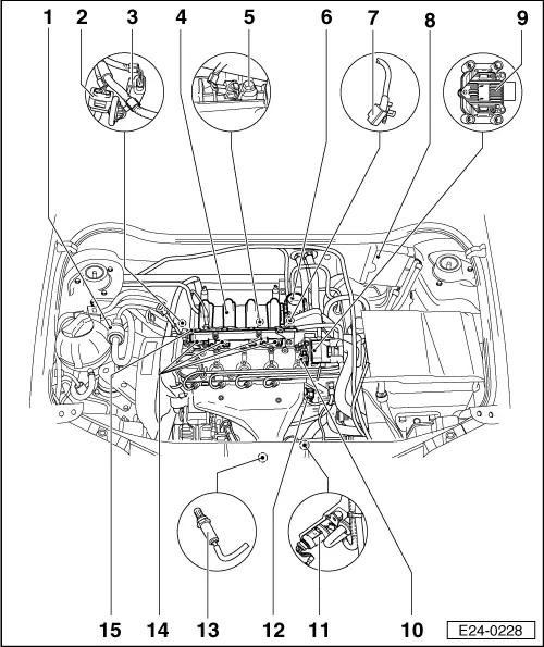
| 1 - | Solenoid valve 1 for activated charcoal filter -N80-*/** |
| q | Checking: → VAS 5051; Vehicle self-diagnosis |
| 2 - | Connector |
| q | Black, 3-pin |
| q | For engine speed sender -G28- |
| 3 - | Connector |
| q | Black, 4-pin |
| q | For intake manifold pressure sender -G71- with intake air temperature sender -G42- |
| q | Contacts gold plated |
| 4 - | Intake manifold |
| q | Removing and installing → Chapter |
| 5 - | Knock sensor 1 -G61-* |
| q | Situated in the cylinder block, intake side |
| 6 - | Throttle valve control unit -J338-* |
| 7 - | Engine speed sender -G28-* |
| q | Situated in the cylinder block, intake side |
| 8 - | Motronic control unit -J220-* |
| q | Connect or disconnect only when the ignition is off |
| q | If replacing, the engine control unit must be adapted to the electronic immobilizer and the throttle valve control unit; adapting components → Chapter |
| 9 - | Ignition transformer -N152-* |
| q | Marked for ignition cables, do not mix up → Item |
| q | Checking → Chapter |
| 10 - | Hall sender -G40-* |
| q | Checking → Chapter |
| q | Contacts gold plated |
| 11 - | Connector |
| q | Black, 4-pin |
| q | For Lambda probe -G39- and heater for Lambda probe -Z19- |
| q | Contacts 3 and 4 gold-plated |
| 12 - | Coolant temperature sender -G62-* |
| q | If necessary, release the pressure in the cooling system before removing |
| q | Resistance values for coolant temperature sender → Fig. |
| 13 - | Lambda probe before catalytic converter-G39-*50 Nm |
| q | Situated in the front exhaust pipe |
| q | Grease thread only with “G5”. “G5” must not get into the slots on the probe body |
| q | Remove and fit with -U-40080- |
| q | In case of leaking, nip open and replace the o-ring |
| 14 - | Injectors -N30-, -N31-, -N32- and -N33-* |
| q | Removing and installing → Chapter |
| q | Checking → Chapter |
| 15 - | Fuel rail |