seat Workshop Repair Guides

SEAT Workshop Service and Repair Manuals

Securing engine to assembly stand > < Removing and installing en- gine
Notes on removing
Notes on removing
  Note!
Check whether a coded radio is installed as during the forthcoming work sequences the battery earth strap must be disconnected. Obtain radio code first if necessary.
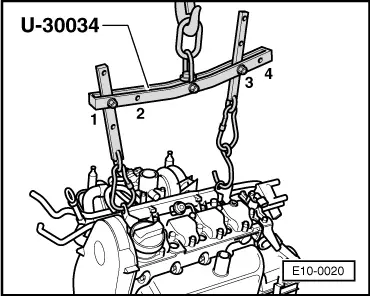
–  The engine is removed forwards together with the gearbox.
–  With ignition switched off disconnect battery earth strap.
–  All cable ties which are opened or cut open when removing engine, must be replaced in the same position when installing engine.
–  Remove air cleaner: → Chapter
–  Remove battery and battery retainer.
–  Open and close the expansion tank sealing cap to release pressure in cooling system.
–  Disconnect all electric wires from gearbox, alternator and starter and move clear.
–  Loosen or separate the following components:
t  The hose from intake manifold to activated charcoal filter system
t  The vacuum hose from inlet manifold to brake servo
t  The connector from coolant temperature sender and oil pressure switch
t  The collective connectors below the thermostat housing
t  The ignition transformer and Hall sender connectors
t  The engine speed sender connector
t  Lambda probe connector in exhaust manifold
t  The 2-pin connector from knock sensor (rear of cylinder block)
–  Now separate fuel supply as well as fuel return pipes at connecting point on suspension strut turret.
  Caution
Fuel supply pipes are under pressure! Before removing from hose connection wrap a cloth around the connection. Then release pressure by carefully pulling hose off connection.
–  Pull off/disconnect all other electrical connections as necessary from engine and lay to one side.
–  Separate front exhaust pipe from exhaust manifold → Chapter, exhaust manifold, front exhaust pipe and catalyst with attachments.
   
–  Unbolt pendulum support at gearbox housing.
–  Disconnect clutch cable: → Rep. Gr.30
–  Disconnect selector mechanism from gearbox. → Rep. Gr.34
–  Drain coolant → Chapter.
–  Loosen hose clips and pull coolant hoses off coolant thermostat housing.
–  Loosen belt pulley securing bolts from power steering vane pump.
–  Remove ribbed belt → Chapter.
  N10-0100
–  Remove power steering vane pump belt pulley securing bolts. Use counterhold -U-40011- when doing this.
–  Unbolt power steering vane pump and secure to sub-frame with wire; hoses remain connected: → Running gear; Rep. Gr.48
–  Remove securing clamps for power steering pressure pipe.
Vehicles with air conditioner
–  Removing air conditioner compressor:
–  Observe additional information and removal instructions → Chapter
Continued for all vehicles
–  Remove left and right-hand drive shaft on gearbox and tie up: → Running gear; Rep. Gr.40
–  Removing lock carrier with attachments: → General body repairs; Rep. Gr.50
  E10-0024
–  Fit lifting beam -U-30034- as follows and lift slightly using a workshop crane:
Pulley end: 2nd hole in hook at position -1-
Flywheel end: 1st hole in hook at position -3-
  Caution
The hooks and locating pins must be secured with locking pins.
  Note!
t  The positions marked -1- and -2- on the bar face towards the belt pulley end.
t  The holes in the hook rails are counted up from the hook.
  E10-0020
–  Unbolt assembly at gearbox and engine mountings.
–  Lower assembly until it is released from the gearbox mounting.
–  Pull assembly out forwards. When doing this, if necessary turn assembly and lower slightly.
  Note!
When the assembly is lifted off, it must be carefully guided to prevent damage to the bodywork.
  N10-0140

Securing engine to assembly stand > < Removing and installing en- gine