
Leon Mk1
| Data bus: checking |
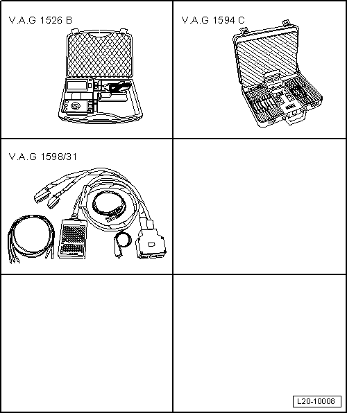
| Special tools and workshop equipment required |
| t | Manual multimeter -VAG 1526B- |
| t | Measuring tool set -VAG 1594C- |
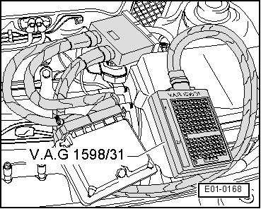
| t | Tester -VAG 1598/31- |
| t | Current flow diagram |
|
|
|
| Tester -VAG 1598/31-, socket | Tester -VAG 1598/31-, socket |
| 58 | 60 |
| Specification: 60 ... 72 Ω | |
|