
Leon Mk1
| Oil sump, oil pump, balance shaft assembly: component overview |
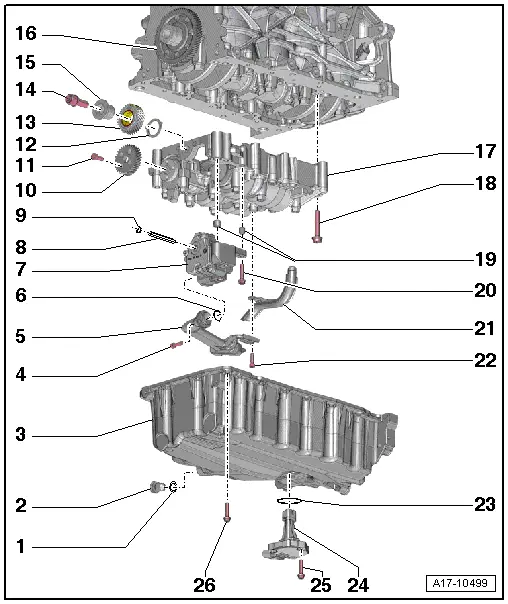
| 1 - | Seal |
| q | Replace |
| 2 - | Oil drain plug |
| q | 30 Nm |
| 3 - | Oil sump |
| q | removing and fitting → Chapter |
| 4 - | Bolt |
| q | 9 Nm |
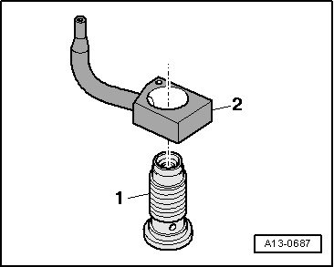
| 5 - | Intake conduit |
| q | Clean strainer if soiled. |
| 6 - | O ring |
| q | Replace |
| 7 - | Oil pump: |
| q | removing and fitting → Chapter |
| q | Before installing, check that the two dowel sleeves for centring oil pump are fitted onto balance shaft assembly |
| 8 - | Oil pump drive shaft |
| 9 - | Circlip |
| q | Must fit securely in groove |
| q | A damaged or excessively widened securing ring must be replaced. |
| 10 - | Spur gear for balance shaft |
| 11 - | Bolt |
| q | Replace |
| q | 20 Nm ± +90° |
| 12 - | Thrust washer |
| q | For idler gear |
| q | Replace |
| q | Installation position → Fig. |
| q | When installing the idler gear,it must be secured with grease on the balancing module |
| 13 - | Idler gear |
| q | Replace |
| q | To achieve the correct backlash a suitably thick coating is already applied to the new idler gear; the required clearance is achieved as the coating is worn down |
| q | On idler gears with coating applied to the teeth on parts of the circumference only, a white dot indicates the correct installation position |
| q | If there is no white dot, the complete circumference of the idler gear is coated |
| q | Fitting position: Part No. must be visible |
| q | Make sure thrust washer is properly seated → Fig. |
| 14 - | Bolt |
| q | Replace |
| q | 90 Nm ± +90° |
| 15 - | Hub |
| q | For idler gear |
| q | Replace |
| 16 - | Crankshaft gear |
| 17 - | Balancer shaft module |
| q | Removing → Chapter |
| q | Re-installing "old" balance shaft assembly → Chapter |
| q | Installing new balance shaft assembly → Chapter |
| q | Before installing, check that the two dowel sleeves for centring balance shaft assembly are fitted on cylinder block |
| 18 - | Bolt |
| q | Replace |
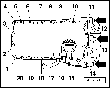
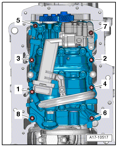
| q | Tightening torque and sequence → Fig. |
| 19 - | Guide sleeve |
| 20 - | Bolt |
| q | 9 Nm |
| 21 - | Oil suction line |
| 22 - | Bolt |
| q | 10 Nm |
| 23 - | Ring seal |
| q | Replace |
| 24 - | Oil level and oil temperature sender -G266- |
| q | removing and fitting → Chapter |
| 25 - | Bolt |
| q | Self-locking |
| q | Replace |
| q | 9 Nm |
| 26 - | Bolt |
| q | Tightening torque and sequence → Fig. |
|
|
|
 Caution
|
|
|
|
|