
Leon Mk1

| 1 - | Conrod bolt - 30 Nm +90° (1/4 turn) further |
| q | Replace |
| q | Oil threads and contact surface. |
| q | To measure the radial play, use used bolts |
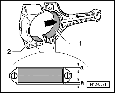
| 2 - | Conrod bearing cap |
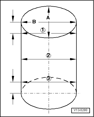
| q | Mark cylinder number -B- |
| q | Fitting position: The marks -A- should point towards the pulley |
| 3 - | Bearing shell |
| q | Installation position → Fig. |
| q | Do not interchange used bearing shells (mark) |
| q | Note design: Upper half-bearing (to piston) made from more resistant material. Distinguishing factors with new bearing shells: Black line on the contact surface in the cutting area |
| q | Check for secure seating. |
| q | Axial clearance: Wear limit: 0.37 mm |
| q | Check radial clearance with Plastigage |
| q | Do not turn crankshaft when measuring radial clearance |
| q | Radial play; wear limit: 0.08 mm |
| 4 - | Conrod |
| q | Replace only in sets |
| q | Mark cylinder number -B- |
| q | Fitting position: The marks -A- should point towards the pulley |
| 5 - | Circlip |
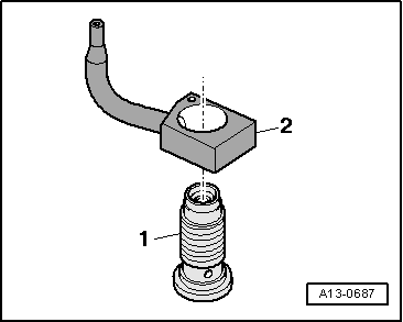
| 6 - | Piston pin |
| q | If difficult to remove, heat piston to approx. 60 °C. |
| q | Remove and install with the installation tool -VW 222A-, see equivalent → Anchor |
| 7 - | Piston |
| q | With combustion chamber |
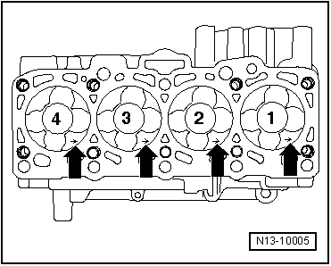
| q | Mark the installation position and the cylinder correspondence |
| q | Installation position and piston/cylinder correspondence → Fig. |
| q | Arrow on piston crown points to belt pulley end. |
| q | If the piston is scratched, replace it |
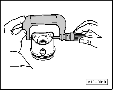
| q | Checking piston → Fig. |
| q | Piston and cylinder dimensions → Chapter |
| q | Checking cylinder bore → Fig. |
| q | Install with piston ring compressor |
| q | Checking piston position at TDC → Chapter |
| 8 - | Piston rings |
| q | Compression rings |
| q | Displace the gaps at 120° from each other |
| q | Use piston ring pliers to remove and install |
| q | „TOP“ must face towards piston crown |
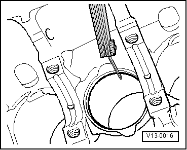
| q | Piston ring ends: check clearance → Fig. |
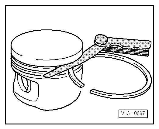
| q | Check play with piston groove → Fig. |
| 9 - | Piston ring |
| q | Oil scraping ring |
| q | Displace the gaps by 120° towards the lower compression ring |
| q | Use piston ring pliers to remove and install |
| q | Piston ring ends: check clearance → Fig. |
| q | Check play with piston groove → Fig. |
|
|
| Piston ring (Dimensions in mm) | new | Wear limit |
| 1. Compression ring | 0,20 … 0,40 | 1,00 |
| 2. Compression ring | 0,20 … 0,40 | 1,00 |
| Oil scraping ring | 0,25 … 0,50 | 1,00 |
|
|
| Piston ring (Dimensions in mm) | new | Wear limit |
| 1. Compression ring | 0,06 … 0,09 | 0,25 |
| 2. Compression ring | 0,05 … 0,08 | 0,25 |
| Oil scraping ring | 0,03 … 0,06 | 0,15 |
|
|
|
|
|
|
|
|
 Note
Note
|
|
|
|
|
|