seat Workshop Repair Guides

SEAT Workshop Service and Repair Manuals

Cooling system components (bodywork side) > < Oil filter bracket, oil radiator and oil supply pipe
Draining off and filling coolant
Consult the equivalence table for tools and equipment according to applicability among Seat / VW / Audi / Skoda → Chapter.
   
Special tools and workshop equipment required
t  Measuring tool -T10007-, see equivalent → Anchor
t  Adapter -VAG 1274/8-, see equivalent → Anchor
t  Adapter -VAG 1274/10-, see equivalent → Anchor
t  Coolant charger -VAS 6096-, see equivalent → Anchor
t  Collecting tray -VAS 6208-, see equivalent → Anchor
t  Pliers for spring-loaded band-type clamps -VAS 6499-, see equivalent → Anchor

Draining off
  WARNING
Hot coolant and vapours can cause burns!
When the engine is hot the cooling system is under pressure.
To reduce the system charge pressure, cover the expansion tank plug with a rag and open carefully.
–  Open filler cap on coolant expansion tank.
   
–  Loosen quick-type locks -1 and 2-, and remove front noise insulation.
  A10-1320
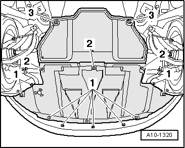
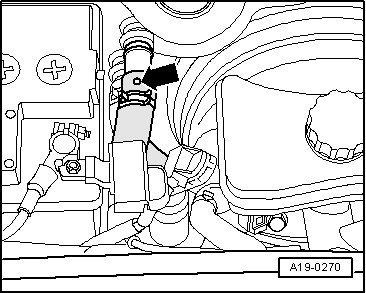
–  Place the drip tray -VAS 6208- under the engine.
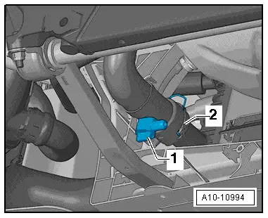
–  Release the drain plug -1- and drain off the coolant.
  Note
Item -2- can be disregarded.
Filling
  Note
t  
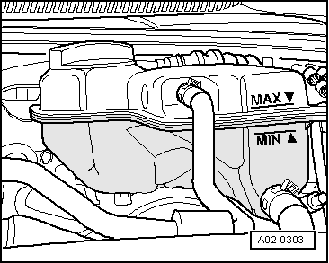
The cooling system is filled all year round with a mixture of water and coolant additive. Mixture ratio → Anchor.
t  Use only the coolant additive listed in the → Spare parts catalogue. Other coolant additives could seriously impair in particular the anti-corrosion properties. The resulting damage could lead to loss of coolant and consequently to serious engine damage.
t  The specified coolant (based on recommended mixture ratio) → Anchor prevents frost and corrosion damage and stops scaling. These also raise the boiling temperature. For these reasons the cooling system must be filled all year round with the correct antifreeze and anticorrosion additive.
t  Thanks to this rise in the boiling point, the coolant guarantees good running, even when the engine undergoes heavy strain, especially in countries with tropical climates.
t  Frost protection must be guaranteed up to approx. –25 °C (in countries with Arctic climate up to approx. -35 ℃).
t  The concentration of the coolant must not be reduced by adding water in summer or in countries with hot climates. The coolant concentration must be at least 40 %.
t  If a higher anti-freeze is required due to the climate, the percentage of the coolant additive can be increased, but only up to 60% (anti-freeze up to approx. -40ºC). If the percentage is higher then the cooling and anti-freeze capacities are reduced.
t  To mix up the coolant use clean drinking-water only.
t  If radiator, heat exchanger, cylinder head, cylinder head gasket or cylinder block have been renewed, do not re-use old coolant.
t  Contaminated or dirty coolant must not be used again.
t  To check the antifreeze protection in the coolant system use the refractometer -T10007-.
Recommended mixture ratio for coolant
l  Coolant (40%) and water (60%) for frost protection to -25 ℃
l  Coolant (50%) and water (50%) for frost protection to -35 ℃
l  Coolant (60%) and water (40%) for frost protection to -40 ℃
t  Coolant: → Spare parts catalogue
  A10-10994
–  Close drain plug -1-.
  A10-10994
–  Fill reservoir of the cooling system charge unit -VAS 6096- with at least 8 litres of pre-mixed coolant (according to recommended mixing ratio):
l  Radiator anti-freeze/anti-corrosion agent (40%) and water (60%) for anti-freeze protection up to -25°C.
l  Radiator anti-freeze/anti-corrosion agent (50%) and water (50%) for anti-freeze protection up to -35°C.
l  Radiator anti-freeze/anti-corrosion agent (60%) and water (40%) for anti-freeze protection up to -40°C.
–  Screw on the Adapter -VAG 1274/8- on the coolant compensation container.
–  Fit the coolant charger -VAS 6096- onto the adaptor -VAG 1274/8-.
–  Lead the air discharge hose -1- in a small container -2-.
  Note
When flashing off a small quantity of coolant is carried away, which is to be collected.
–  Close both valves -A- and -B- and turn lever at right angles to direction of flow.
–  Connect hose -3- to compressed air.
l  Pressure: 6 ... 10 bar
  A19-0351
–  Open the valve -B- (lever in the direction of flow).
l  The suction pump generates vacuum in the cooling system. The arrow of the indicating instrument must move in the green range.
–  Also open the valve -A- briefly. For this purpose, turn the lever in the flow direction so that hose on the coolant reservoir of coolant filling unit -VAS 6096- can fill with coolant.
–  Close valve -A- again.
–  Leave the valve -B- open for 2 further minutes.
l  The suction pump generates vacuum in the cooling system. The arrow of the indicating instrument must move in the green range.
–  Close valve -B-.
l  The arrow of the indicating instrument must move in the green range. Then the vacuum in the cooling system is sufficient for the subsequent filling.
  Note
t  If the arrow falls below the green range, repeat the procedure.
t  If the vacuum drops, the cooling system must be checked for possible leakages.
–  Disconnect the compressed air hose.
–  Open valve -A-.
l  The vacuum in the cooling system causes the coolant to be sucked in from the container of the coolant filling unit -VAS 6096- and thus the cooling system is filled.
–  Remove the cooling system charge unit -VAS 6096- from the adapter -VAG 1274/8- on the coolant expansion tank.
  A19-0353
–  Mount the adapter -VAG 1274/10- onto adapter -VAG 1274/8-.
  A19-0065
Release the coolant hose leading to the heat exchanger and withdraw it till the breather hole in the coolant hose -arrow- is not covered by the connection any more.
–  Refill the coolant till it escapes from the breather hole in the coolant hose.
–  Push coolant hose back onto connection and secure with spring-type hose clip.
–  On vehicles with auxiliary heater, switch heater on (for about 30 seconds) and then off again.
–  Close the filler cap of the coolant expansion tank.
–  Start the engine.
–  Set temperature to „HI“ in all zones.
–  Switch off air conditioner compressor (press ECON button).
–  Let the engine run for three minutes at 2000/min.
–  Allow engine to run at idling speed until two large coolant hoses at radiator become warm.
–  Let the engine run for one minute at 2000/min.
–  Switch off ignition and allow engine to cool down.
–  Install the front sound installation → Rep. gr.66.
  WARNING
Hot coolant and vapours can cause burns!
When the engine is hot the cooling system is under pressure.
To reduce the system charge pressure, cover the expansion tank plug with a rag and open carefully.
  A19-0270
–  Check coolant level.
l  The coolant level must be at the MAX marking when the engine is cold.
l  The coolant level can be above the MAX marking when the engine is warm.
  A02-0303

Cooling system components (bodywork side) > < Oil filter bracket, oil radiator and oil supply pipe