seat Workshop Repair Guides

SEAT Workshop Service and Repair Manuals

Checking charge air system > < Exhaust gas turbocharger : Assembly overview
Removing and installing turbocharger
t  Removing → Anchor
t  Installing → Anchor
Consult the equivalence table for tools and equipment according to applicability among Seat / VW / Audi / Skoda → Chapter.
Special tools and workshop equipment required
   
t  
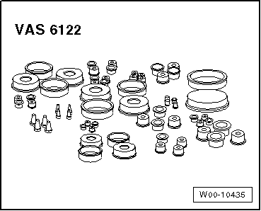
Plug set for engine -VAS 6122-, see equivalent → Anchor
  Caution
If the turbocharger has suffered mechanical damage (e.g. damaged compressor wheel), it is not sufficient merely to fit a new turbocharger. To avoid any subsequent damage, the following work must be carried out:
t  Check the air filter housing, the air filter element and the air intake hose for dirt.
t  Check the complete process of the charge air circuit and the charge air cooler for foreign particles.
t  If foreign objects are discovered in the charge air system, clean the charge air path and, if necessary, renew the charge air cooler.
  W00-10435
Removing
–  Disconnect the engine cover-arrow-.
  E10-10060
–  Remove air cleaner housing → Chapter.
–  Release the quick fasteners -1... 3- and remove the noise insulation in the front and back.
  A10-1320
–  Disconnect exhaust system at clamp -arrow-.
  A26-10015
–  Unscrew bolt -1- from front exhaust pipe
  Note
Item -2- can be disregarded.
  A26-10120
–  Disconnect air intake hose from turbocharger -arrow-.
  A21-10357
–  Loosen the bolts -1- and -2-, and remove the turbocharger bracket.
  A21-10303
–  Unscrew bolts -1- and union nut -2-; remove oil return line.
  Note
Place a cloth underneath to catch any escaping oil.
–  Unplug electrical connector -3- on exhaust gas temperature sensor 1 -G235-.and release.
  A21-10305
–  Loosen bolts -arrows- and lay bearing -1- down to side.
  A10-11107
–  Unscrew the securing nuts -1- of the connection between the exhaust turbocharger/exhaust manifold which are reachable from the bottom.
  A21-10311
–  Remove the crankcase breather line -1- from the cylinder head cover and place it aside.
–  Release the hose clip -2- and remove the air intake hose.
  A21-10304
–  Pull off vacuum hose -1-.
–  Remove bolts -2-.
–  Unscrew the bolts -4- with the wrench -3320-.
  Note
Ignore position -3-.
  A21-10306
–  Unscrew the bolts -arrows- and detach the exhaust gas recirculation radiator.
–  Remove cooler for exhaust gas recirculation and lay coolant hoses -1- and -2- down to side.
  A21-10307
–  Unscrew nuts -1, 2, 3- from exhaust gas turbocharger and separate particle filter from exhaust gas turbocharger.
  A26-10168
–  Expose electrical line for exhaust gas temperature sensor 1 -G235--item 1- in engine block -arrow-.
  A26-10680
–  Unscrew the union nut -1- from the oil supply pipe of the turbocharger.
–  Detach the depression hose -2-.
–  Unplug the connector -3- of the position sender for the charge pressure actuator -G581-.
–  Unscrew the securing nut (which is reachable from the top) -4- of the exhaust turbocharger on the exhaust manifold and remove the exhaust turbocharger.
–  Close open line and connection by positioning clean covers included in set of engine lock covers -VAS 6122-.
  Note
t  Danger of damaging oil return line
t  After removing the turbocharger, do not put it down so it rests on the top section of the oil return line – this could cause damage.
Installing
Installation is carried out in reverse order. The following should be taken into account:
  Note
t  Always replace gaskets, O-rings and self-locking nuts.
t  Charge the turbocharger with engine oil using the connection sleeve of the oil supply pipe.
t  The supercharger air system should not leak
t  The brackets for the hoses and the supercharger air system tubes must be free from oil and grease for fitting.
t  Secure all hose connections with the correct type of hose clips (same as original equipment) → Spare parts catalogue.
t  Observe the correct installation position of the hose connections of the charged-air system in order to enable the markings to be aligned correctly.
t  To ensure that the charge air hoses can be connected securely, you must spray the screws on used screw-type clips with rust remover prior to installation.
t  After installing exhaust turbocharger, allow engine to idle for approx. 1 minute to ensure that the turbocharger is lubricated.
–  Install the cooler for the exhaust gas recirculation cooler system → Chapter.
–  Mount the particle filter → Chapter.
–  Align exhaust system without tension → Chapter
–  Check oil level → Chapter.
Tightening torques
  A21-10308
ComponentNm
Turbocharger to exhaust manifold25 1)2)
Support for turbocharger to turbocharger20
Support for turbocharger to cylinder block40
Oil return pipe to the engine block40
Oil supply pipe to the turbocharger22
Oil supply pipe bracket to the exhaust manifold22
Air intake hose to turbocharger8
Hose clips (9 mm wide)3,5
Hose clips (13 mm wide)5,5
Exhaust gas temperature sender 1 -G235-45 Nm
l  1) Renew bolts.
l  2) Apply hot bolt paste; hot bolt paste → Spare parts catalogue.


Checking charge air system > < Exhaust gas turbocharger : Assembly overview