seat Workshop Repair Guides

SEAT Workshop Service and Repair Manuals

Diesel direct injection system > < Intake manifold: Assembly overview
Intake manifold: removing and installing
t  Removing → Anchor
t  Installing → Anchor
Consult the equivalence table for tools and equipment according to applicability among Seat / VW / Audi / Skoda → Chapter.
   
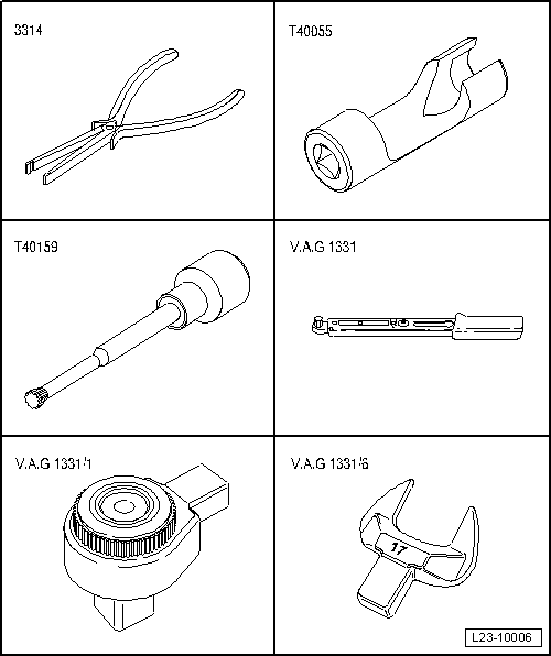
Special tools and workshop equipment required
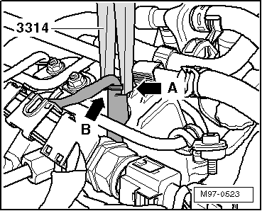
t  Base -3314-, see equivalent → Anchor
t  Socket wrench insert -T40055-, see equivalent → Anchor
t  Socket XZN 8 -T40159-, see equivalent → Anchor
t  Torque wrench (5... 50 Nm) -V.A.G 1331-, see equivalent → Anchor
t  Ratchet 1/2' x 9-12 -VAG 1331/1-, see equivalent → Anchor
t  Insert e/c 17 terminal -V.A.G 1331/6-, see equivalent → Anchor

Removing
  WARNING
t  Always read rules for cleanliness and instructions for working on fuel system → Chapter.
t  Follow these instructions and rules for cleanliness before starting work and while working on the fuel system.
   
–  Disconnect the engine cover-arrow-.
–  Take noise insulation off cylinder head cover.
  Caution
Pay particular attention not to damage the wires when removing the connections, because otherwise it would be necessary to replace the entire wiring harness. Do not press pliers -3314- together excessively when removing the connection, because otherwise the bearing supports could be damaged.
  E10-10060
–  Put the pliers -3314- into the groove -arrow A- on the collar of the support sleeve -arrow B-.
  M97-0523
–  Remove the connectors -5, 6, 7 and 8- from the spark plugs.
  A23-10265
–  Unscrew union nuts on high pressure pump -1- and the high pressure reservoir -5- to remove high pressure fuel line -4-.
–  Unscrew bolts -arrows- from fuel high pressure line.
–  Lay wiring harness -6- at one side.
  A23-10273
–  Remove both fuel supply lines -2 and 3- from the high pressure pump.
  A23-10273
–  Remove bolts -arrows- securing the two fuel pipes.
  Note
The fuel pipes must not be kinked.
  Caution
t  Mark assignment of high pressure lines on cylinders. They must always be re-installed on the same cylinders.
t  Observe rules for cleanliness when working on the injection system.
t  Plug open connections with suitable sealing caps immediately.
–  Unscrew the union nuts for high-pressure pipes on injectors using socket -T40055- , 17 mm.
–  Loosen union nuts on high pressure lines with socket wrench attachment SW 17 -V.A.G 1331/6- on high pressure reservoir.
–  Place the removed high-pressure lines on a clean cloth.
  A23-10272
–  Unplug the following connectors.
1 - Fuel pressure sender -G247-
2 - Fuel pressure regulating valve -N276-
3 - Variable intake manifold motor -V183-
4 - Intake manifold flap motor -V157-
5 - Exhaust gas recirculation valve: -N18-
  A23-10264
–  Remove high pressure reservoir, for this purpose loosen bolts -2-.
  A23-10272
–  Open the hose clip -arrow- of the air intake hose and remove under the intake manifold flap motor -V157-.
–  Unscrew the bolt of the oil dipstick bracket.
–  Remove the exhaust gas recirculation connecting pipe from the exhaust gas recirculation valve -N18-.
–  Remove bolts securing intake manifold in diagonal sequence starting from outside and working inwards using socket XZN 8 -T40159-.
–  Remove the intake manifold.
Installing
Installation is carried out in the reverse sequence; note the following:
–  Renew seals and gaskets.
–  Tighten bolts securing intake manifold in diagonal sequence starting from outside and working inwards.
t  Tightening torque of the intake manifold to cylinder head → Item.
t  Tightening torque of the exhaust gas recirculation joint hose → Chapter.
t  Tightening torque of the high pressure lines → Chapter
  A24-10598

Diesel direct injection system > < Intake manifold: Assembly overview