
Leon Mk1
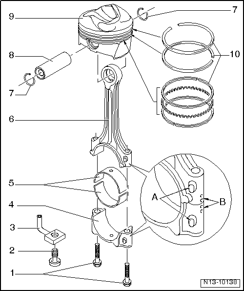
| 1 - | Conrod bolt, 30 Nm +90° (1/4 turn) |
| q | Replace |
| q | Oil threads and contact surface. |
| q | To measure radial play, tighten to 30 Nm, without retightening |
| 2 - | Fastening bolt with drain valve, 27 Nm |
| q | Opening pressure 1.3 - 1.6 bars |
| 3 - | Oil spray jet |
| q | For piston cooling |
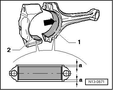
| 4 - | Conrod bearing cap |
| q | Note fitting position: |
| q | Rods divided by fracturing (cracking) can only be fitted in one position and only with the corresponding conrod |
| q | Mark cylinder number -B- |
| q | Fitting position: Marking -A- towards the pulley end |
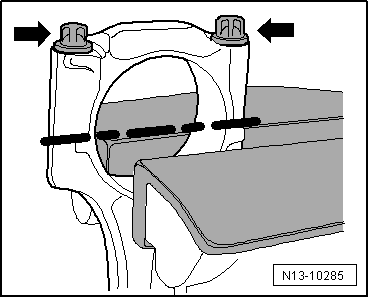
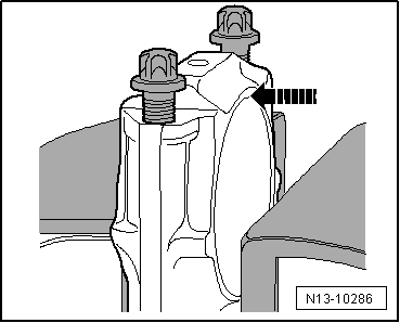
| 5 - | Bearing cap |
| q | Note installation position → Fig. |
| q | Do not interchange used bearing shells. |
| q | New axial play: 0.10 - 0.35 mm; Wear limit: 0.4 mm |
| q | Checking radial clearance with Plastigage: new: 0.02 - 0.06 mm; Wear limit: 0.09 mm when measuring the radial play, do not rotate the crankshaft |
| 6 - | Conrod |
| q | With industrially cracked conrod cap. |
| q | Renew as set only. |
| q | Mark cylinder number -B- |
| q | Fitting position: Marking -A- towards the pulley end |
| 7 - | Circlip |
| 8 - | Piston pin |
| q | If difficult to move, heat piston to 60 °C |
| q | Remove and install with the installation tool -VW 222A-, see equivalent → Anchor |
| 9 - | Piston |
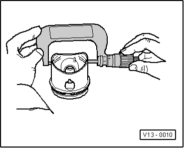
| q | Checking → Fig. |
| q | Mark installation position and cylinder number. |
| q | Arrow on piston crown points to pulley end |
| q | Install using piston ring clamp |
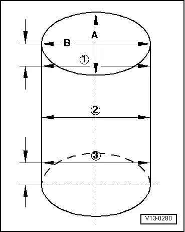
| q | Checking cylinder bore → Fig. |
| q | Piston and cylinder dimensions → Chapter |
| 10 - | Piston rings |
| q | Offset gaps by 120° |
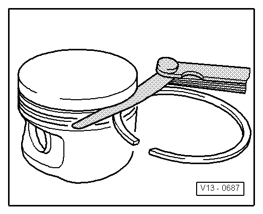
| q | Use piston ring pliers to remove and install |
| q | The marks point towards the piston crown. |
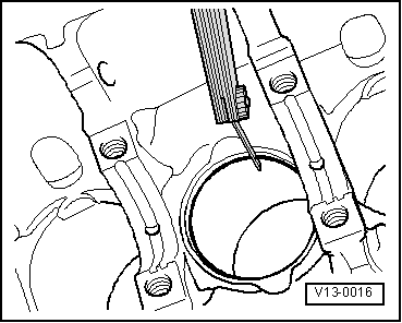
| q | Checking ring gap → Fig. |
| q | Checking ring-to-groove clearance → Fig. |
 Note
Note
|
|
|
|
|
|
|
|
| Piston ring | Clearance between ends | ||
| When new | Wear limit | ||
| Compression rings | mm | 0,20 - 0,40 | 0,8 |
| Oil scraping ring | mm | 0,25 - 0,50 | 0,8 |
|
|
| Piston ring | Clearance | ||
| When new | Wear limit | ||
| Compression rings | mm | 0,06 - 0,09 | 0,20 |
| Oil scraping ring | mm | 0,03 - 0,06 | 0,15 |
|
|
Note
|
|