seat Workshop Repair Guides

SEAT Workshop Service and Repair Manuals

Valve control > < Piston and cylinder dimensions
Removal:
Removal:
  Caution
When doing any repair work, especially in the engine compartment, pay attention to the following due to the cramped conditions:
t  All the various lines (e.g. fuel, hydraulic system, active carbon filter system, coolant, refrigerant, brake fluid and vacuum pipes and hoses) and electrical wiring must be installed in their original positions.
t  To prevent damaging the hoses, ensure that all mobile or hot components are easily accessible.
–  Remove the air filter housing → Chapter
–  Remove upper notched belt guard.
–  Remove the centre soundproofing → Bodywork, exterior assembly work; Rep. Gr.50.
–  Remove front right hand side wheel housing protection: → Bodywork, exterior fitting work; Rep. Gr.50.
–  Mark direction of rotation of Poly-V belt and remove → Chapter
   
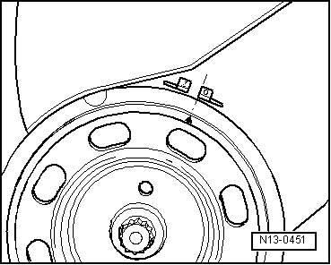
–  Set the crankshaft to the top dead centre of cylinder 1. The groove on the pulley must be aligned with the edge of the marking -O- .
  N13-0451
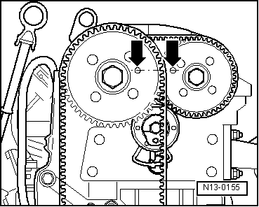
–  The locking spaces on the camshaft sprockets should line up with the spaces on the camshaft housing -arrows-.
  Note
If the marks are on opposite sides of the notched belt sprockets, turn the crankshaft one more turn.
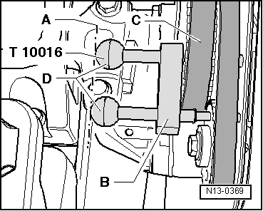
Immobilise both camshaft sprockets using the camshaft fastener -T10016-, as follows:
  N13-0155
–  Insert both locking pins through the locking spaces on the camshaft sprockets, as far as the end point on the spaces on the camshaft housing.
  Note
The two locking pins are correctly fitted if the final parts -D- are in line with line -A-.
–  Insert support -B- as far as possible in the intake camshaft wheel -C-.
  N13-0369
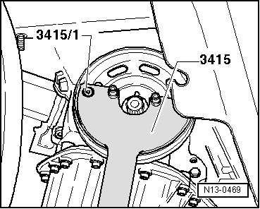
–  Loosen the bolt fixing the pulley and the sprocket of the notched belt. Immobilise the pulley with the retaining tool -3415- and the bolt -3415/1-.
–  Remove pulley. Screw back the bolt with two washers to hold timing belt wheel in place.
–  Install lower notched belt guard.
  N13-0469
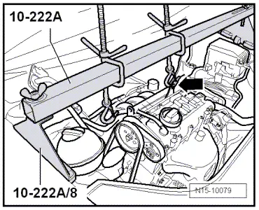
–  Attach the suspension tool -10-222A- as shown with legs -10-222A/8-, and support the engine in the assembly position.
  N15-10079
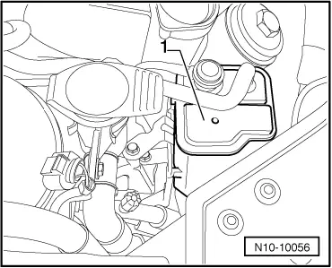
–  Remove the activated carbon filter -1- from the support.
–  Remove the filling mouth from the windscreen washer.
  N10-10056
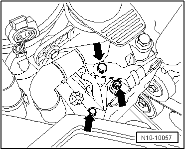
–  Remove the activated carbon filter support -arrows- from the engine support.
–  Remove the coolant tank, and leave to one side. (With the hoses still attached).
  N10-10057
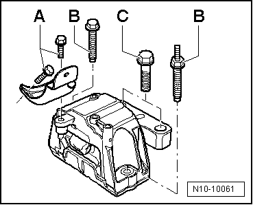
–  Undo the bolts -A-, -B- and -C- of the support unit on the side of the pulley and remove the support unit completely.
–  Remove the engine support from the cylinder head attachment.
–  Mark the toothed belt D.O.R.
Removing principal notched belt
  N10-10061
–  Release the principal belt tension roller -1- and release the timing belt by turning the tension roller anticlockwise -arrow-.
–  Free the clamp bolt of the tension roller.
–  Remove the notched belt .
Remove the branch derived from notched belt.
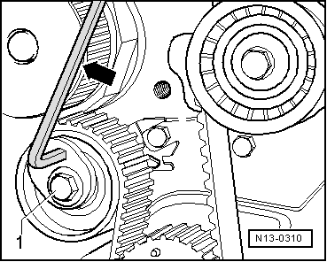
  N13-0310
–  Release the tension roller from the branch derived from the notched belt -1- and release the notched belt by rotating the tension roller clockwise.
–  Remove the branch derived from timing belt.
–  Remove the notched belt .
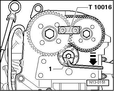
  N13-0151

Valve control > < Piston and cylinder dimensions