
Leon Mk1
 Note
Note
|
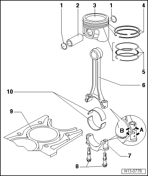
| 1 - | Securing ring |
| 2 - | Piston pin |
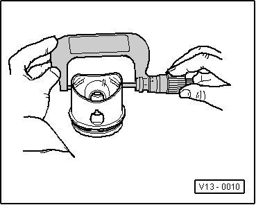
| q | If difficult to move, heat piston to 60 °C |
| q | Remove and install with the awl -10-14-, see equivalent → Chapter |
| 3 - | Piston |
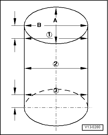
| q | check → Fig. |
| q | Mark installation position and cylinder number. |
| q | Arrow on piston crown points to pulley end |
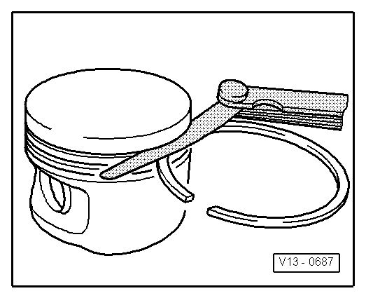
| q | Install using piston ring clamp |
| 4 - | Compression rings |
| q | Shift the gap by 120º |
| q | Remove and install compression rings using piston ring pliers |
| q | The mark “TOP” must face towards piston crown |
| q | Checking end clearance → Fig. |
| q | Checking piston ring side clearance → Fig. |
| 5 - | Oil scraper rings |
| q | Carefully remove and install by hand the oil scraper rings made up of 3 parts |
| q | Checking end clearance → Fig. |
| q | The play between the rings and the grooves cannot be measured |
| 6 - | Conrod |
| q | Renew as set only. |
| q | Mark cylinder assignment -A- |
| q | Fitting position: The marks -B- should point in the direction of the pulley |
| q | Piston axial guided |
| 7 - | Conrod bearing cap |
| q | Rods divided by fracturing (cracking) can only be fitted in one position and only with the corresponding conrod |
| 8 - | Conrod bolt |
| q | M7×0,75: 20 Nm + retighten 1/4 turn (90º) |
| q | M8x1: 30 Nm + retighten 1/4 turn (90º) |
| q | Replace. |
| q | Oil threads and contact surface. |
| q | To measure radial play, tighten to the applicable torque, without retightening |
| 9 - | cylinder block |
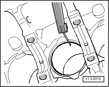
| q | Checking cylinder bore → Fig. |
| q | Piston and cylinder dimensions → Chapter |
| 10 - | Bearing shell |
| q | Do not interchange used bearing shells |
| q | Centrally align bearing shells on insertion |
| Check radial clearance with Plastigage |
Note| Do not rotate crankshaft when checking radial clearance. |
| q | New: 0.020… 0.061 mm |
| q | Wear limit: 0.091 mm |
|
|
| Piston ring Dimensions in mm | New | Wear limit |
| 1. st compression ring | 0,20...0,50 | 1,0 |
| 2ºcompression ring | 0,40...0,70 | 1,0 |
| Oil scraper ring | 0,40...1,40 | --- → Note |
|
|
|
| Piston ring Dimensions in mm | New | Wear limit |
| 1. st compression ring | 0,04...0,08 | 0,15 |
| 2ºcompression ring | 0,04...0,08 | 0,15 |
| Oil scraper ring | not measurable | |
|
|
Note
|
|