
Leon Mk1
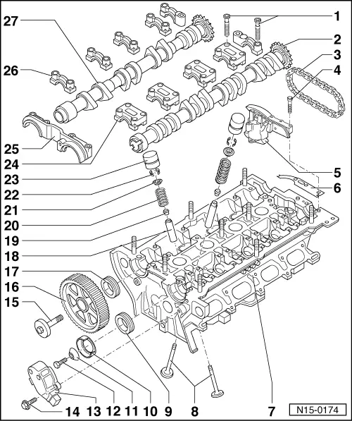
| Repairing valve gear |
 Note!
Note!| t | Cylinder heads which have cracks between the valve seats or between a valve seat insert and the spark plug thread can be used further without reducing service life, provided the cracks do not exceed a maximum of 0.3 mm in width, or when no more than the first 4 turns of the spark plug thread are cracked. |
| t | When new bucket tappets have been installed the engine must not be started for about 30 minutes. (Otherwise valves will contact pistons.) Then turn crankshaft two full revolutions. |
| 1 - | 10 Nm |
| 2 - | Inlet camshaft |
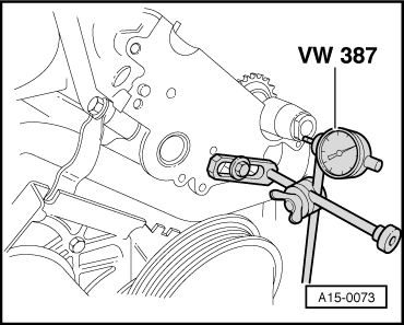
| q | Checking axial clearance → Fig.. |
| q | Removing and installing → Chapter. |
| q | Check radial clearance with plastigage, wear limit: 0.1 mm. |
| q | Runout: max. 0.01 mm. |
| 3 - | Drive chain |
| q | Before removing, mark direction of rotation (installation position) → Chapter, Removing and installing camshafts. |
| 4 - | 10 Nm |
| 5 - | Chain tensioner |
| q | Must seat on dowel sleeves. |
| q | Only rotate engine when chain tensioner is installed. |
| q | Secure with chain tensioner retainer -3366- before removing → Chapter, Removing and installing camshafts. |
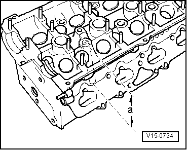
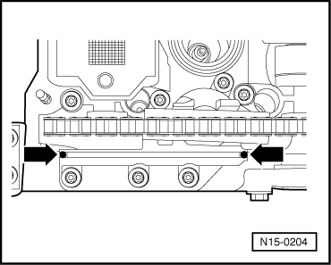
| q | Seal transitions between chain tensioner/cylinder head → Fig. |
| 6 - | Rubber/metal gasket |
| q | Replacement → Chapter, Removing and installing camshafts. |
| 7 - | Cylinder head |
| q | Removing and installing → Chapter. |
| q | Reworking valve seats → Chapter. |
| q | Reworking sealing surface → Fig.. |
| q | Sealing transition points → Fig. and → Fig.. |
| 8 - | Valves |
| q | Do not rework, only lapping-in is permitted. |
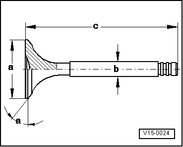
| q | Valve dimensions → Fig.. |
| q | Exhaust valves with sodium filling: Observe disposal instructions → Fig.. |
| 9 - | Seal |
| q | Renewing → Chapter. |
| 10 - | Trim |
| q | For Hall sender. |
| q | When installing note fixing arrangement. |
| 11 - | Washer |
| q | Conical. |
| 12 - | 25 Nm |
| 13 - | Hall sender -G40- housing |
| q | Check Hall sender -G40- → Rep. Gr.28. |
| 14 - | 10 Nm |
| 15 - | 65 Nm |
| q | Use counterhold tool -3036- to loosen and tighten |
| 16 - | Camshaft pulley |
| q | Note installation position: the narrow web of camshaft pulley faces outwards and the TDC No. 1 cylinder marking is visible. |
| q | Note position when installing toothed belt → Chapter, removing, installing and tensioning toothed belt. |
| 17 - | Seal |
| q | Renewing → Chapter. |
| 18 - | Valve guide |
| q | Checking → Chapter. |
| 19 - | Valve stem oil seal |
| q | Renewing → Chapter. |
| 20 - | Valve spring |
| q | Removing and installing: |
| Cylinder head removed: With valve spring tool -3362- and press piece -3362/1-. |
| Cylinder head installed: → Chapter, Renewing valve stem oil seals |
| 21 - | Valve spring plate |
| 22 - | Cotters |
| 23 - | Bucket tappet |
| q | Do not interchange. |
| q | With hydraulic valve clearance compensation. |
| q | Checking → Chapter. |
| q | Store with cam contact surface downwards |
| q | Before installing, check camshaft axial clearance → Fig.. |
| q | Oil contact surface. |
| 24 - | Inlet camshaft bearing cap |
| q | Observe installation position and installation sequence → Chapter, Removing and installing camshaft. |
| 25 - | Double bearing cap |
| q | Must seat on dowel sleeves. |
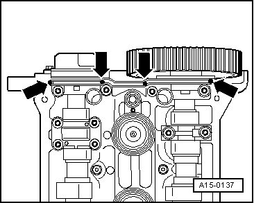
| q | Lightly coat contact surface with sealing compound -AMV 174 004 01-, observe installation position and installation sequence → Chapter, Removing and installing camshaft. |
| q | Seal transition points between double bearing cap and cylinder head → Fig.. |
| 26 - | Exhaust camshaft bearing cap |
| q | Observe installation position and installation sequence → Chapter, Removing and installing camshaft. |
| 27 - | Exhaust camshaft |
| q | Checking axial clearance → Fig.. |
| q | Removing and installing → Chapter. |
| q | Check radial clearance with plastigage, wear limit: 0.1 mm. |
| q | Runout: max. 0.01 mm. |
|
|
Note!
|
|
| Dimension | Inlet valve | Exhaust valve | |
| Ø a | mm | 26.9 | 29.9 |
| Ø b | mm | 5.963 | 5.943 |
| c | mm | 104.84...105.34 | 103.64...104.14 |
| α | ∠° | 45 | 45 |
Note!
|
|
|
|
|