seat Workshop Repair Guides

SEAT Workshop Service and Repair Manuals

Exhaust turbocharger, G-charger > < Adjusting accelerator cable
Checking accelerator pedal position sender
   
Checking accelerator pedal position sender
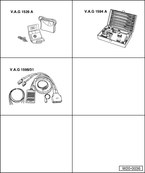
Special tools and workshop equipment required
t  Hand multimeter -V.A.G 1526 A- or hand multimeter -V.A.G 1526C-
t  Auxiliary measuring set -V.A.G 1594 A- or auxiliary measuring set -V.A.G 1594C-
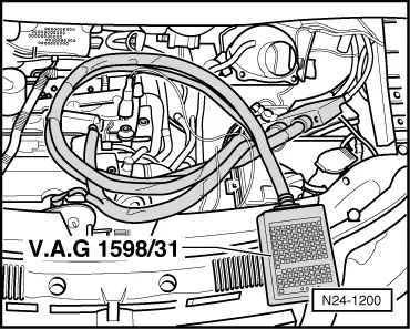
t  Adapter lead, 121-pin -V.A.G 1598/31-

Not illustrated:
t  Fault reader -V.A.G 1551- or vehicle system tester -V.A.G 1552- or vehicle diagnosis and service information system -VAS 5052-
t  Current flow diagram
Function
Both accelerator position sender -G79- and accelerator position sender 2 -G185- are located on the accelerator pedal and transmit the driver's command to the engine control unit completely independently of one another. Both senders are installed together in a housing.
Test prerequisites
   
l  Fuses must be OK.
l  The battery voltage must be at least 11.5 V.
l  All electrical consumers, e.g. lights and rear window heating, must be switched off.
l  If the vehicle is equipped with an air conditioner, it must be switched off.
Test procedure
–  Connect fault reader -V.A.G 1551- or vehicle system tester -V.A.G 1552- or vehicle diagnosis and service information system -VAS 5052- and select engine control unit with “address word” 01. Ignition must be switched on for this → Rep. Gr.01.
  N01-0485
Indicated on display:
–  Press keys 0 and 8 for function “Read measured value block” and confirm entry with Q key.
 
Rapid data transfer                 HELP
Select function XX                      
Indicated on display:
–  Press keys 0, 6 and 2 for “Display group number 62” and confirm entry with Q key.
 
Read measured value block               
Input display group number XXX          
Indicated on display: (1...4 = display zones)
–  Check specification from accelerator position sender -G79- at idling speed stop in display zone 3. Specification: 6…96 %.
–  Check specification from accelerator position sender 2 -G185- at idling stop in display zone 4. Specification: 3...48 %.
  Note!
The engine control unit calculates the angle sender voltage value as a percent of 5 Volts and displays this percentage. (5 Volt supply voltage equals 100 %).
–  Slowly depress accelerator pedal down to full throttle position and observe the percentage display in display zones 3 and 4:
The percent figures in display zone 3 must rise evenly. The tolerance range of 6...96 % is not covered completely.
The percent figures in display zone 4 must rise evenly. The tolerance range of 3...48 % is not covered completely.
  Note!
The figure displayed in display zone 3 must always be approximately double that displayed in display zone 4.
–  Press the key.
–  Press keys 0 and 6 for function “End output” and confirm entry with Q key.
–  Switch off ignition.
If the display does not indicate as described:
–  Check accelerator position sender voltage supply and wiring connections → Anchor.
Checking voltage supply and wiring to control unit
–  Pull 6-pin connector off accelerator position sender.
–  Switch on ignition.
–  Connect multimeter for measuring voltage to the following connector contacts using auxiliary cables from auxiliary measuring set -V.A.G 1594C-.
Contact 1 + earth
Contact 1 + 5
Contact 2 + earth
Contact 2 +3
 
Read measured value block 62          -
         1         2         3         4
Specification: at least 4.5 V
–  Switch off ignition.
If no voltage is present:
–  First check whether a coded radio is fitted. If so, obtain anti-theft coding.
–  Remove battery.
  N20-10151
–  Connect adapter lead, 121-pin -V.A.G 1598/31- to control unit wiring harness. The engine control unit remains disconnected.
–  Check cables between test box and 6-pin connector for open circuit using current flow diagram.
Contact 1 and test box socket 72
Contact 2 and test box socket 73
Contact 3 and test box socket 36
Contact 4 and test box socket 35
Contact 5 and test box socket 33
Contact 6 and test box socket 34
  N24-1200
Cable resistance: max. 1.5 Ω.
–  Also check wiring for short to one another, short to vehicle earth and short to battery positive. Specification: ∞ Ω.
If no fault in lines is detected:
–  Renew accelerator position sender → Item.
–  Reading and erasing fault memory → Rep. Gr.01.
Vehicles with 5-speed automatic gearbox 09B
–  On vehicles with an automatic gearbox the gearbox control unit must additionally be adapted: → Rep. Gr.01.
  N20-10151

Exhaust turbocharger, G-charger > < Adjusting accelerator cable