
Leon Mk1
| Checking exhaust gas recirculation potentiometer -G212- |
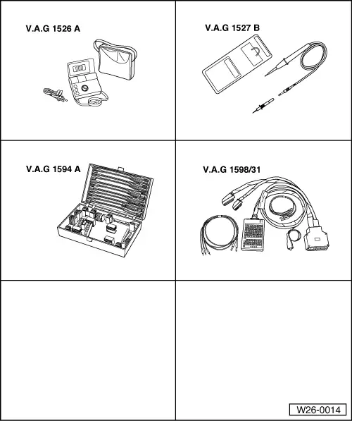
| Special tools and workshop equipment required |
| t | Hand multimeter -V.A.G 1526A- or hand multimeter -V.A.G 1526C- |
| t | Voltage tester -V.A.G 1527B- |
| t | Auxiliary measuring set -V.A.G 1594 A- or auxiliary measuring set -V.A.G 1594C- |
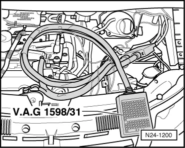
| t | Adapter cable, 121-pin -V.A.G 1598/31- |
|
|
|
|
|
|
|
|
|
|
|