
Leon Mk1
| Piston, connecting rod, and casing: removing and installing |

| 1 - | Safety cotter pin |
| 2 - | Piston pin |
| q | If movement is sluggish, heat the piston to 60 °C |
| q | Remove and install with -T20019- |
| 3 - | Piston |
| q | Mark the fitting position and correspondence with respective casing/cylinder |
| q | The arrow on the piston head indicates the engine's turning direction (towards the camshaft side) |
| q | Install with casing to fit rings |
| q | Only install pistons of the same weight category (+ or - on the piston head) |
| q | Only available as a replacement part together with the casing |
| 4 - | Piston rings |
| q | Stagger the cuts by 120° |
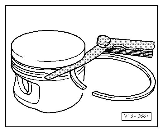
| q | Remove and install the compression rings using ring pliers |
| q | Carefully remove and install by hand the 3 piece oil scraper rings |
| q | The inscription “TOP” should must indicate the piston head |
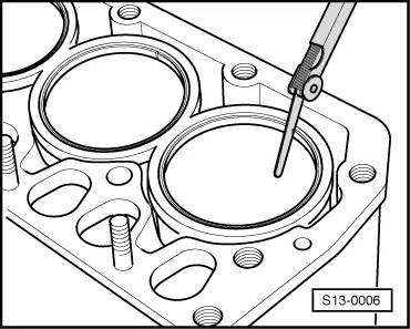
| q | Check the play between the ends of the rings → Fig. |
| q | Check the coupling play between the rings and the grooves in the piston → Fig. |
| 5 - | Connecting rod |
| q | Replacement part only available as a complete set (four rods) |
| q | Mark correspondence to cylinder → Item |
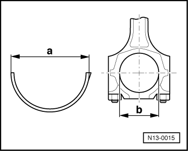
| q | Fitting position: The marks -B- must point towards the distribution |
| q | Axial guidance by piston |
| 6 - | Connecting rod caps |
| q | In the case of fractured or “cracked” connecting rods, the cap can only be fitted in one position and only on its corresponding connecting rod |
| 7 - | Connecting rod bolt, 20 Nm + 1/4 of turn (90°) |
| q | Renew |
| q | Lubricate the threads and the contact surface |
| q | In order to measure radial play, tighten to 20 Nm, without retightening |
| 8 - | Engine block |
| q | The surfaces where the casings will go must be clean and even |
| q | Remove dirt and grime from the surfaces only by cleaning; do not use sandpaper, scraper or the like |
| 9 - | Half bearings |
| q | Fit the centred half bearings |
| q | Do not interchange the used half bearings |
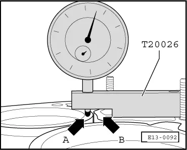
| q | Measure pre-tension → Fig. |
| q | Measure radial play with Plastigage: New: 0.020...0.061 mm Wear limit: 0.091 mm When measuring radial play do not turn crankshaft |
| 10 - | Washer |
| q | Renew |
| q | To correct the casing's pre-tension |
| 11 - | Casing |
| q | Observe the weight category (+ or - on the piston head) |
| q | Only available as a replacement part together with the the piston |
| q | Measure the pre-tension → Fig. |
| Piston ring Dimensions in mm | New | Wear limit |
| 1st compression ring | 0.20...0.50 | 1.0 |
| 2nd compression ring | 0.20...0.50 | 1.0 |
| Scraper ring | 0.40...1.40 | -- → Note |
|
|
|
| Piston ring Dimensions in mm | New | Wear limit |
| 1st compression ring | 0.04...0.08 | 0.15 |
| 2nd compression ring | 0.04...0.08 | 0.15 |
| Scraper ring | not measured | |
|
|
 Note!
Note!
|
|