seat Workshop Repair Guides

SEAT Workshop Service and Repair Manuals

Exhaust turbocharger, G-charger > < Fuel supply system: repairing
Nozzle: Removing and installing
t  Nozzle: Removing → Anchor
t  Nozzle: Installing → Anchor.
t  Tightening torque → Anchor
Consult the equivalence table for tools and equipment according to applicability among Seat / VW / Audi / Skoda → Chapter.
Special tools and workshop equipment required
   
t  Spanner -T10202-, see equivalent → Anchor
Removing .
Please observe safety precautions → Chapter.
Observe rules for cleanliness → Chapter.
l  To dismount the spray jet, the fuel tank should be, at maximum, at 1/3 of its capacity. Empty the fuel tank if necessary → Chapter
–  Remove rear right seat → Bodywork - Interior fitting work; Rep. gr.72.
  W00-1334
–  Unclip the tabs -arrows- of the right lock clamp cover.
  A20-1206
–  Unplug the connector -arrow- of the lock clamp
  A20-10130
–  Mark the supply hoses -1- and the return -2- of fuel.
  WARNING
t  The fuel system is pressurised. Before opening the system place a cloth around the connection. Then release pressure by carefully loosening the connection.
t  The fuel hoses temperature or of the fuel itself may reach in extreme cases up to 100 ºC after the engine is switched off. Before opening the duct connections, allow the fuel to cool otherwise there is a risk of severe burns.
t  Wear protective gloves.
t  Wear eye protection.
–  Detach the two locking clamp hoses by pressing the clips to unlock them.
  A20-1213
–  Unscrew lock nut using wrench -T10202-.
  Caution
Open the locking clamp only with the fuel tank at 1/3 of its capacity, at most. Otherwise a large amount of fuel will be spilled.
  A20-10236
–  Remove through the fuel tank opening the right lock clamp and the O-ring of the fuel supply unit and leave them to one side without detaching the conduits.
–  Access through the fuel tank opening, separate the conduit -1- to the spray jet, for this press the clip to release it.
–  Remove the fuel supply conduit -2- of the fuel supply unit.
  A20-10381
–  Unclip the tabs -arrows- of the left lock clamp cover.
  A20-1216
–  Unplug the connector -1- of the lock clamp
–  Unhook the connector -2- and set it aside.
  A20-10093
–  Unscrew lock nut using wrench -T10202-.
  A20-10236
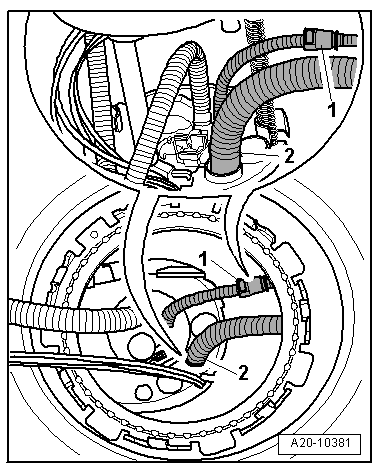
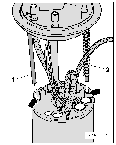
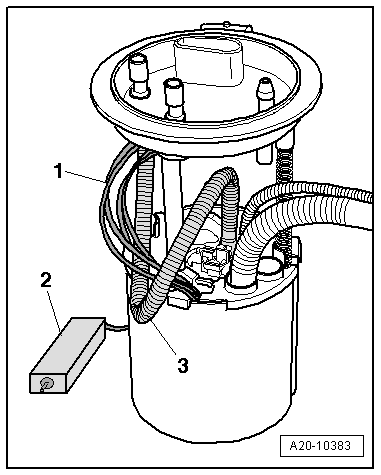
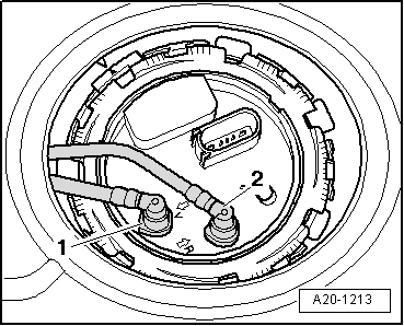
–  Carefully pull the fuel level sender 2 -G169-- 2- with the spray jet -1-,removing them a little through the fuel tank opening.
–  Remove the seal ring.
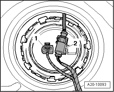
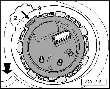
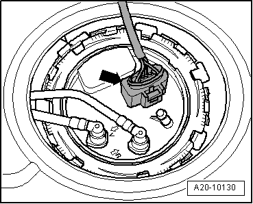
–  Unclip the spray jet from the locking flange -arrows-.
  Note
On removing the fuel level sender 2 -G169-, make sure you do not bend its floater arm.
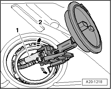
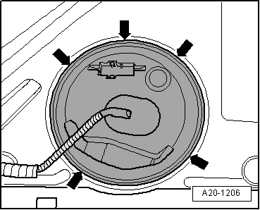
–  On the vehicle left side, put your hand through the fuel tank opening and remove the nozzle together with the conduits pulling towards the left.
Fitting .
Installation is carried out in the reverse order; note the following:
  Note
Upon introducing the fuel level sender 2 -G169-, make sure you do not bend its floater arm.
–  On the vehicle left side, insert the nozzle with the conduits via the fuel tank opening.
  A20-1218
–  On the vehicle right side, put your hand through the fuel tank opening and place the nozzle together with the conduits in the fitting position.
–  Introduce the fuel supply conduit -2- until it is heard to engage in the opening of the fuel supply unit.
–  Attach the conduit -1- to the spray jet until hearing it engage.
  Note
  A20-10381
For better clarity, the next two images show the fuel supply unit without the fuel tank.
–  Mount the new gasket ring of the lock bridle (it should be dry).
–  Engage the guide-tubes -1- and -2- of the locking flange in the guide-conduits -arrows- of the fuel supply unit.
  A20-10382
–  Make sure that the electrical wires -1-and the fuel supply hose -3- stay as shown in the figure, so that they do not block the lever sender -2-.
  A20-10383
–  Tighten downwards the locking flange using force until leaving it in its fitting position.
l  The clip -2- of the blind flange is positioned in the direction of the arrow and should be located the tongues -1- and -3- of the fuel tank.
  Note
The -arrow- points forwards.
  A20-1215
–  Tighten the lock ring.
  A20-10236
–  Carefully insert the fuel level sender 2 -G169--2- through the opening in the fuel tank.
–  Engage the spray jet -1- in the locking flange -2- until hearing it engage.
  A20-1218
–  Mount the new gasket ring of the lock bridle (it should be dry).
–  Note the installation position of the sealing flange:
l  The clip -2- of the blind flange is positioned in the direction of the arrow and should be located the tongues -1- and -3- of the fuel tank.
  Note
The -arrow- points forwards.
  A20-1219
–  Tighten the lock ring.
–  Install the rear right seat → Bodywork - Interior fitting work; Rep. gr.72.
–  After fitting the fuel supply unit, you must fill 5 litres, at least.
Tightening torque
  A20-10236
ComponentNm
Locking ring of the fuel supply unit / Locking flange of the fuel level sender 2 -G169-110


Exhaust turbocharger, G-charger > < Fuel supply system: repairing