seat Workshop Repair Guides

SEAT Workshop Service and Repair Manuals

Assembly mountings > < Safety precautions
Engine: dismounting
   
Engine: dismounting
Check the tool and equipment equivalence table according to the applicability between Seat / VW / Audi / Skoda → Chapter
Special tools and workshop equipment required
t  counterhold -2024A-, see equivalent → Anchor
t  Hose clamp -3094-, see equivalent → Anchor
t  Hydraulic jack -VAG 1383A-, see equivalent → Anchor
t  Collecting tray -VAS 6208-, see equivalent → Anchor
t  Workshop crane -VAS 6100-, see equivalent → Anchor
t  Pliers for spring-loaded band-type clamps -VAS 6499-, see equivalent → Anchor

   
t  Socket -10 222A-, see equivalent → Anchor
t  Shackle -10 222A/12-, see equivalent → Anchor.
t  Lever -80 200-, see equivalent → Anchor
t  Adjustment tool -T40098-, please see Correspondence → Anchor
t  Engine sealing plug set -VAS 6122-, see equivalent → Anchor
t  Base -VAS 6340-, see equivalent → Anchor

   
t  Gearbox mounting -T10337-, see equivalent → Anchor
  W00-10418
t  Release tool -T40138-, see equivalent → Anchor
Operation process
  WARNING
Make sure the vehicle cannot tip over when the engine is removed.
Secure the vehicle. For this the luggage compartment must be empty.
  Note
t  Lift out engine without gearbox.
t  Collect drained coolant in a clean container for re-use or disposal.
t  The cable ties must be installed in their same place again.
  Caution
Risk of severe damage to the electronic components when disconnecting the battery.
Observe the correct procedure for disconnecting the battery → Rep. gr.27.
  W00-10552
–  Disconnect battery earth cable -arrow- with ignition switched off.
  WARNING
Hot vapour/hot coolant may escape when opening expansion tank. Cover cap with cloth and open carefully.
–  Open the Sealing plug of the coolant expansion tank.
–  Remove both front wheels.
  E27-10033
–  Loosen the fasteners -2-, -3- and -5- and remove the front noise insulation.
–  Remove front left and front right wheel housing liners → Rep. gr.66.
  A10-1307
–  Unbolt bracket for soundproofing -arrows-.
–  Remove the front bumper cover → exterior body installation work; Rep. gr.63.
  A10-0968
–  Remove air ducts in front of charge air coolers (left and right) -arrows-.
–  Place the drip tray -VAS 6208- under the engine.
  A21-0199
–  Open the drain screw -1- on the coolant hose and let the coolant drain. Then disconnect the connecting support -2- from the radiator.
  A10-10994
–  Remove the air hose -1- between the charged air cooler left and the lock carrier.
  WARNING
The air conditioning refrigerant circuit must not be opened.
–  Disengage refrigerant line at bracket -2-.
  A10-10312
–  Detach air intake hose -1- going to turbocharger (bottom right).
–  Separate the air hose to the charged air cooler at the lock carrier -2-.
  A10-10311
–  Pull off engine cover panel -arrows-.
  E10-10100
–  Unscrew both bolts-arrows- for the air pipes -1- on the lock carrier plate.
–  Remove the air conduit -1- from the air filter housing.
  E24-10062
–  Disconnect top coolant hose -1- at radiator.
–  Pull out the connector -2- of the airbag sensors to the left and right of the lock carrier.
  A10-0955
–  Unplug the connector -Arrow- of the headlight on both sides of the vehicle.
  A10-0953
–  Take electrical connectors -1- and -2- out of retainer and disconnect them.
–  Move electrical wiring clear.
  A10-10282
–  Suspend the temperature sensor for outside temperature -G17--2- from the bracket.
  Note
Ignore positions -3-, -4- and the -arrows-.
–  Detach electrical connector -1- at high-pressure sender -G65-.
  WARNING
The air conditioning refrigerant circuit must not be opened.
  Note
In order to avoid damage to the condenser or the pipes/hoses of the refrigerant, avoid pulling, bending or twisting excessively.
–  Hang out the control cable on the engine hood lock.
–  Move lock carrier to service position → Rep. gr.50.
–  Remove the Poly V-belt → Chapter.
  A10-0897
–  Disconnect connector -arrow- on oil level and oil temperature sender -G266-.
  A17-0215
–  Unscrew bolt -3- and remove torque reaction support -1-.
  A34-10504
–  Unscrew the bracket of the refrigerant line -Arrow- from the oil sump.
  A10-10286
–  Unplug the connector -1- of the line to the magnetic clutch of the air conditioning compressor.
  Caution
The air conditioning refrigerant circuit must not be opened.
–  Unscrew the bolts -arrow- for air conditioner compressor.
  Note
In order to avoid damage to the condenser or the pipes/hoses of the refrigerant, avoid pulling, bending or twisting excessively.
–  Suspend air-conditioner compressor with connected lines from the left longitudinal member of the vehicle.
  A10-10234
–  Unscrew the earth cable -1-.
–  Disconnect vacuum hose going to brake servo at bulkhead -2-.
–  Disconnect ACF hose -3-.
  A10-10319
–  Detach the coolant hoses -1-, -2- and -3- and unscrew the coolant expansion tank -arrow-.
–  Separate the connector of the switch for coolant shortage indicator -F66- below on the coolant compensation tank.
  E10-10101
–  Unplug electrical connector from charge air pressure sender -G31--1-.
–  Remove charge air hose (left-side) -2-.
  A10-10320
–  Remove charge air hose (right-side) -1-.
  A10-10324
–  Detach electrical connector -1- for Lambda probe after catalytic converter -G130- and Lambda probe 1 heater, after catalytic converter -Z29- (brown connector) from retainer.
–  Detach electrical connector -2- for Lambda probe -G39- and Lambda probe heater -Z19- (black connector) from retainer.
  Caution
Observe rules for cleanliness when working on the fuel supply system.
  Caution
The fuel pressure must be reduced prior to opening any components in the high-pressure section of the fuel system. The flow → Rep. gr.24 must be absolutely maintained.
  A10-10322
–  Disconnect fuel supply hose -1- and fuel return hose -2-.
  A20-10457
–  Disconnect the coolant hose to the heat exchanger of the heater in the rear section of the engine -3- and -4-.
  Note
Positions -1-, -2- and -5- can be disregarded.
–  Remove wind moulding → Outer body and assembly work; Rep. gr.50.
  A10-11051
–  Remove cover for electronics box in plenum chamber -arrows-.
  A10-0996
–  Use screwdriver to pry off retaining strap -arrows-.
  A10-0997
–  Unlock the capture hooks -arrows- toward outside and remove retaining bracket.
  A91-0820
–  Remove all plug connections from the bar -2-.
–  Unscrew electrical line connector -1-.
  A10-1000
–  Release retaining clips -arrows- and lift auxiliary relay carrier out of electronics box.
–  Disengage engine wiring harness at electronics box and bulkhead and move clear.
  WARNING
Correctly fasten engine control unit to engine so that it is not subjected to jolts when removing the engine and cannot fall down.
–  Place wiring harness together with engine control unit on engine and secure against falling down and jolts.
  A10-1001
–  Thread off the front screws -arrow- of the propeller pump through the openings of the V ribs belt pulley.
  E10-10102
–  Unscrew the screw -1- of the continued coolant circulation pump -V51- and place the pump to one side with the lines connected.
  Note
Disregard items -2- and -arrows-.
  A19-10770
–  Unscrew the rear screws -arrow- of the vane pump.
–  Put down the propeller pump on the side on the longitudinal spar. Lines remain connected.
  A10-0966
–  Loosen the bracket -1-, disconnect the air hose and place to the side.
–  Disconnect the connector -2- from the air mass meter -G70-.
–  Unclip cable harness from air cleaner housing and lay down to side.
–  Loosen expansion clip -3- and separate air cleaner housing.
–  Pull upward to loosen lower mounts and to remove air cleaner housing.
  A10-10325
–  Unscrew earth cable -arrow- from longitudinal member (right-side).
  A10-10313
–  Remove bolts -arrows- and detach heat shield for drive shaft (right-side).
  A37-10841
–  Unscrew the bolts -arrows- of the half shaft / gearbox.
–  Set down with half shaft on the gearbox facing downwards
  Note
Never bend the damping element on the front section of the exhaust pipe with particulate filter more than 10°, otherwise it can be damaged.
  A40-10210
–  Loosen clamping sleeve -arrows- and push to rear.
  A26-10538
–  Unfasten connection -1-, remove bolt -2- and take out mounting for catalytic converter.
  A21-10310
–  Unscrew the nuts -arrows- and remove the front section with catalytic converter downwards.
  A21-10320
–  Unplug electrical connector -arrow- from reversing light switch -F4- and move wire leading to wiring harness clear.
  A10-10318
–  Unplug the electrical connector -3-. For this purpose, slide the locking element to rear and press down the release catch.
–  Detach electrical wire -2- on the starter.
–  Unscrew bolts -1- and -4- of the starter.
–  Unhook the electric cables of the starter from the bracket and lay aside.
–  Remove the starter and place between the cylinder head and engine block.
  Note
On removal, note down bolt length and original installation position for re-installation purposes.
  A27-10148
–  Unscrew engine/gearbox securing bolts -arrows- accessible from below.
  A17-10067
–  Mark positions of bolt connections -1- and locating sleeves -2- on bottom of engine mountings (left and right).
  Note
Different mounting holes are provided for the different engine versions.
–  Unscrew nuts -1- (bottom) at engine mountings (left and right).
  A10-1274
–  Unscrew nut -arrow- at top of engine mounting (left-side).
–  Unscrew top bolts on engine/gearbox assembly flange; leave one bolt in place (finger-tight).
–  Position hydraulic lifter below gearbox without making contact (do not raise vehicle).
  WARNING
Accidents can be caused if parts of the support bracket are not correctly secured.
The hook attachments and locating pins on the lifting tackle must be secured with locking pins -arrows-.
  A17-0210
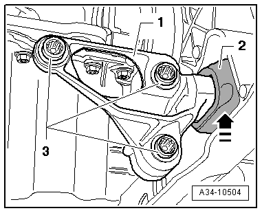
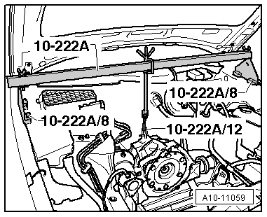
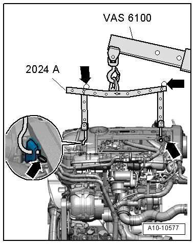
–  Engage lifting tackle -2024A- on engine and workshop hoist -VAS 6100-.
  Note
For illustration purposes here shown with engine removed.
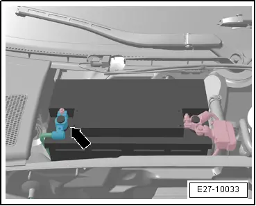
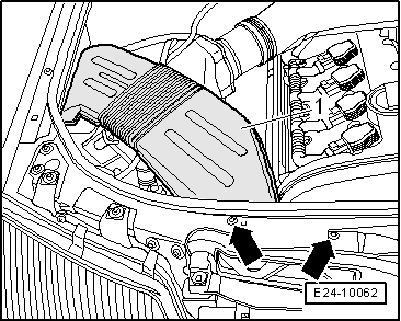
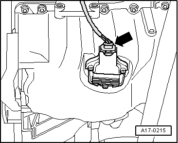
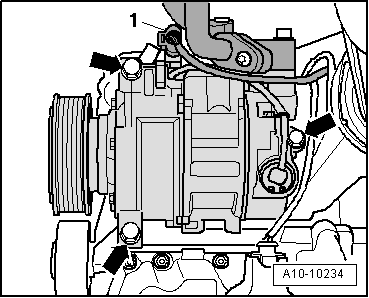
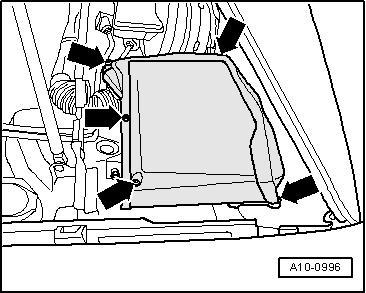
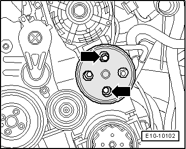
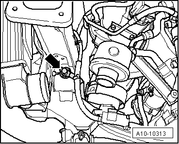
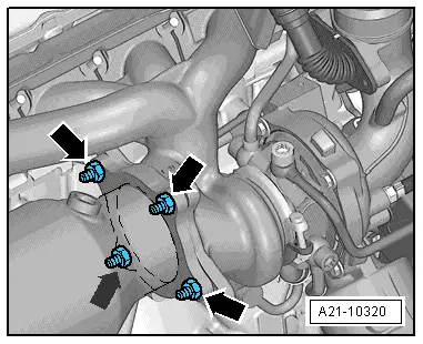
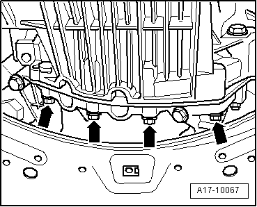
–  Unscrew and remove the last connecting screw on the flange of the engine/gear.
  Caution
Danger of damage to hoses, pipes and wiring connections and to engine compartment.
t  
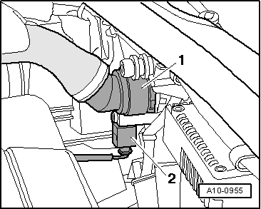
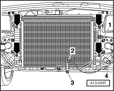
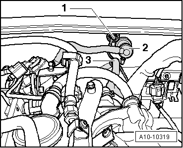
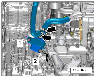
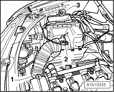
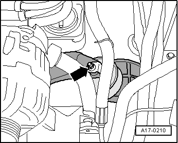
Check that all hoses and cable connections between the engine, gearbox, subframe and body have been detached.
t  Carefully guide engine out of engine compartment when lifting out.
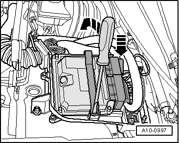
–  Position hydraulic lifter upward until gearbox makes contact.
  Note
Make sure no wires/pipes are damaged at the top on the bulkhead.
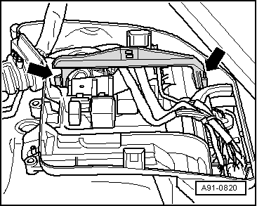
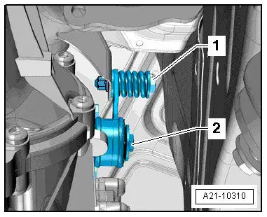
–  Lift the engine with the garage crane -VAS 6100- until the engine bearing thread bolts are free.
  Note
t  
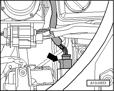
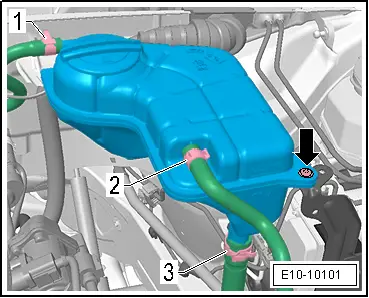
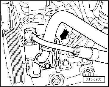
Check that all hoses and line connections between engine and body have been released.
t  Guide »engine« carefully when removing to prevent damage to bodywork.
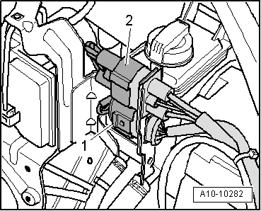
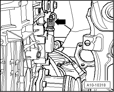
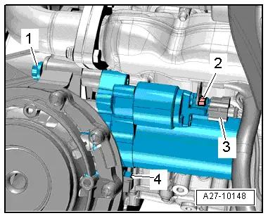
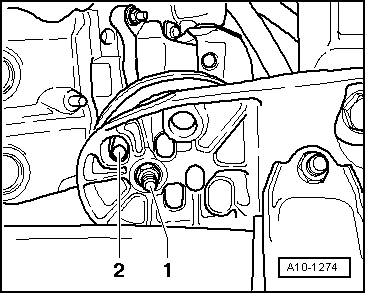
Take special care that the starter is removed at the exact point when separating the engine from the gearbox.
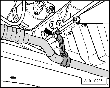
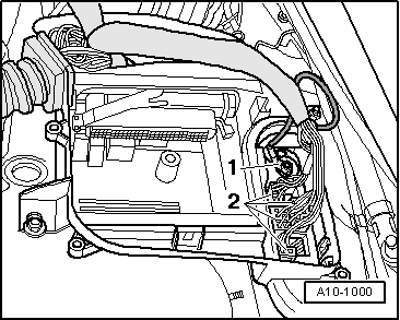
–  Detach engine from gearbox and lift engine forwards out of engine compartment.
  A10-10577
–  Install the support bracket -10 222A- with the adapter -10 222A/8- and attach to the upper sill as shown in the figure.
–  Joint the gearbox and the spindle using the shackles -10 222A/12-.
–  Pre-tension the spindle of support bracket -10 222A- slightly.
–  Remove the hydraulic lifter from the gearbox.
  A10-11059

Assembly mountings > < Safety precautions