
Leon Mk1
 Note
Note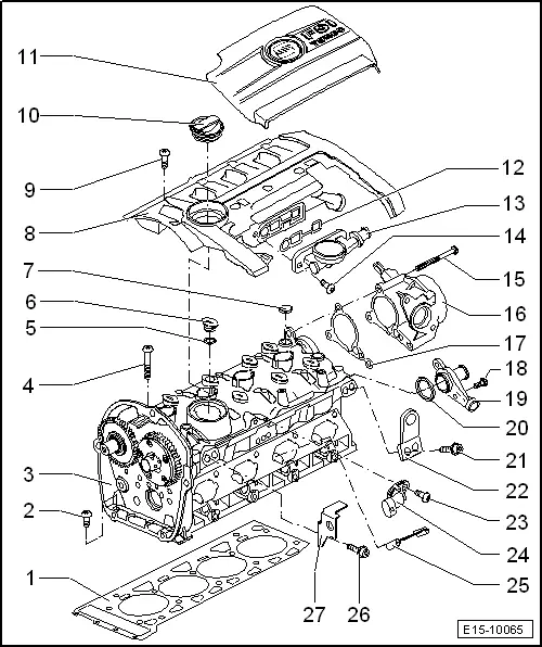
| 1 - | Cylinder head gasket |
| q | Replace |
| q | Note the fitting position: The component number faces towards the cylinder head |
| 2 - | Bolt. |
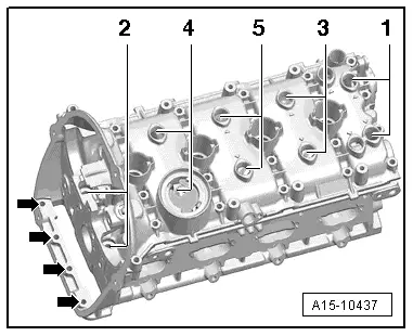
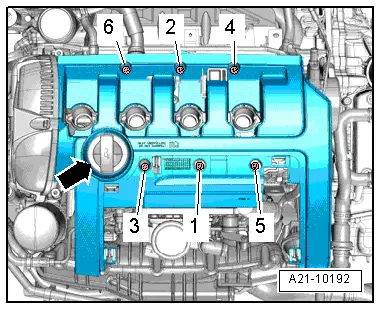
| q | Tightening sequence → Fig. |
| 3 - | Cylinder head |
| q | Removing and installing → Chapter. |
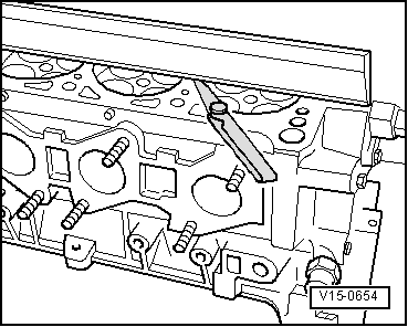
| q | Checking for distortion → Fig. |
| 4 - | Cylinder head bolt |
| q | Replace |
| q | Correct sequence when slackening → Fig. |
| q | Note correct sequence when tightening → Fig. |
| 5 - | O ring |
| q | Replace |
| q | Lubricate with engine oil |
| 6 - | Plug |
| 7 - | O ring |
| q | Replace |
| q | Lubricate with engine oil |
| 8 - | Cover with oil separator |
| q | Removing and installing → Chapter. |
| 9 - | Bolt. |
| q | Tightening sequence → Fig. |
| 10 - | Oil filler cap |
| q | With gasket |
| 11 - | Engine cover panel |
| q | Removing and installing → Chapter. |
| 12 - | Seal |
| q | Renew if damaged or leaking |
| 13 - | Valve body |
| 14 - | Bolt. |
| q | 4.2 Nm. |
| 15 - | Bolt. |
| q | 9 Nm. |
| 16 - | Vacuum pump |
| q | Removing and installing → Chapter. |
| 17 - | Seal |
| q | Replace |
| 18 - | Bolt. |
| q | 9 Nm. |
| 19 - | Joint mouth |
| 20 - | O ring |
| q | Replace |
| q | Lubricate with coolant |
| 21 - | Bolt. |
| q | 25 Nm. |
| 22 - | Transport plate |
| 23 - | Bolt. |
| q | 9 Nm. |
| 24 - | Hall sender -G40- |
| 25 - | Separating plate |
| 26 - | Bolt. |
| q | 25 Nm. |
| 27 - | Transport plate |
|
|
|

|
|
|
|
|