seat Workshop Repair Guides

SEAT Workshop Service and Repair Manuals

General diagram of the exhaust gas turbocharger supercharger air system (engine code BYT) > < Charge air system
Charge air cooling - exploded view
  Note
t  The supercharger air system should not leak
t  The flexible hose sleeves and the other turbocharger air system hoses must be free from oil and grease before the assembly.
t  Apply a lubricant for rubbers free from silicone and oil on the leaking surface and on the joint ring. Do not use lubricant products containing silicone or oil.
t  Replace the joint rings where damaged.
t  On replacing the joint ring, place it on the turbocharger hose groove and check that the joint rings cover the entire groove perimeter to prevent damage.
t  Secure all hose connections with the correct hose clips (same as original equipment) → Spare parts catalogue.
t  
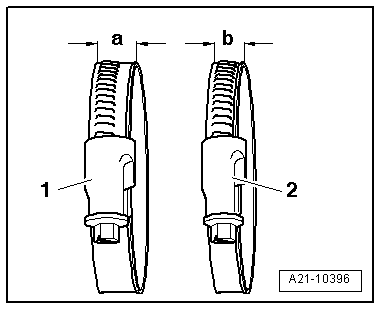
To fix the turbocharger hoses to their connection sleeves safely, if already used clamps are used, their bolt threads should be sprayed with an anti-corrosion spray before the assembly.
   
1 - 5 Nm
2 - Support
q   For intercooler
3 - Charge air cooler
q   Removing and installing → Chapter
4 - Charge air pipe
5 - 10 Nm
6 - From turbocharger
7 - Charge air hose
8 - To the throttle valve control unit -J338-
9 - Charge air hose
10 - 10 Nm
11 - 5 Nm
12 - Intake manifold pressure sender -G71-
13 - Charge air pipe
14 - Charge air hose

   
Attach air hoses with screw clamps (engine code CCZB)
  Note
To ensure that the air hoses can be connected securely, you must spray the screw threads on used screw-type clips with rust remover prior to installation.
Specified torques for
1 - Hose clamp-a- = 13 mm wide: 5.5 Nm
2 - Hose clamp-b- = 9 mm wide: 3 Nm
  A21-10396

General diagram of the exhaust gas turbocharger supercharger air system (engine code BYT) > < Charge air system