| –
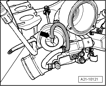
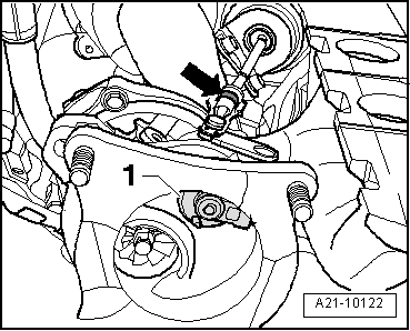
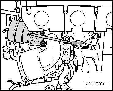
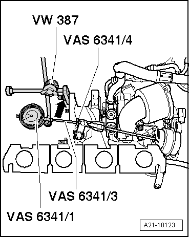
| Attach the universal dial gauge support -VW 387- to the turbocharger -arrow-. |

Note | The values in mm refer to the read value (includes 1 mm pretension). |
| –
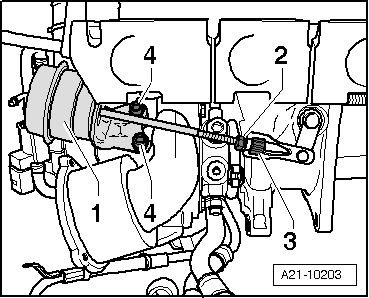
| Secure the dial gauge -VAS 6341/1- with the extension 30 mm -VAS 6341/3- and the flat probe -VAS 6341/4- to the universal dial gauge support -VW 387-. |
| –
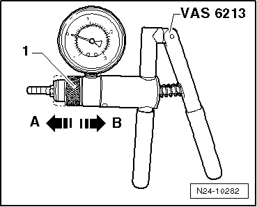
| At 0 bar, tense the gauge -VAS 6341/1- to 1 mm. |
| –
| Position the indicator of the dial gauge -VAS 6341/1- at 0. |
| –
| Ensure that all of the mobile elements of the gauge move smoothly. |
| –
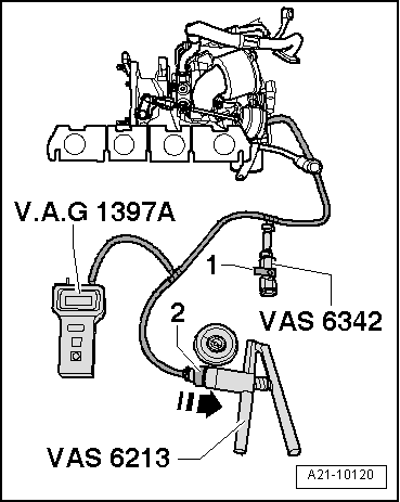
| Operate hand vacuum pump -VAS 6213- until turbocharger tester -V.A.G 1397A- indicates 460 +/- 5 mbar. |
| –
| The gauge should indicate between 4.1 and 4.3 mm; otherwise rotate the knurled nut until this value is indicated. |
| –
| Tighten the lock nut by hand. |
| –
| Repeat measurement procedure. |
| –
| Lower the pressure to 0 mbar with the pressure regulating valve -VAS 6342-. |
| –
| Set the dial gauge -VAS 6341/1- to 0. |
Note | The following measurements should be made in sequence. In the meantime, pressure must not drop to zero. |
| –
| Operate hand vacuum pump -VAS 6213- until turbocharger tester -V.A.G 1397A- indicates 460 +/- 5 mbar. |
| –
| Read and note the value indicated by the gauge -VAS 6341/1-. |
| –
| Operate hand vacuum pump -VAS 6213- until turbocharger tester -V.A.G 1397A- indicates 650 to 700 mbar. |
| –
| Vent system via pressure control valve -VAS 6342- so that pressure reading drops to 460 +/- 5 mbar. |
| –
| Read and note the value indicated by the gauge -VAS 6341/1-. |
| –
| Add the values 1 and 2, and divide the result by 2. |
| –
| The result (average value) must be 5 +/- 0.25 mm. |
| –
| If the result (average value) is not 5 +/- 0.25 mm, correct the adjustment, tighten the locknut by hand and repeat the measurement. |
| –
| If an average result of 5 +/- 0.25 mm, tighten the counter nut to 9 Nm and secure using seal resin → parts catalogue. |
|
|
|