
Leon Mk1
| General plan of fitting points |
| Components A to E are not shown in the illustration. |
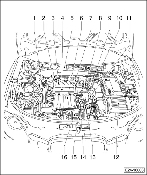
| 1 - | Fuel supply line |
| q | From fuel filter → Item |
| 2 - | Intake manifold pressure sender -G71- with air intake temperature sender -G42- |
| q | Intake manifold and accessory parts - component overview → Chapter |
| 3 - | Lambda probe -G39- (before catalytic converter) 55 Nm |
| q | The screw thread on the new lambda probe is coated with a special paste; the paste must not get into the slots on the probe body |
| q | If a lambda probe is reused, apply paste to the bolts when warm; the paste must not get into the slots on the probe body. Locking fluid for hot working bolts → Parts catalogue |
| q | Remove and install with wrench kit -3337- → Chapter |
| 4 - | Intake manifold upper part |
| q | With intake manifold change-over |
| q | Removing and fitting → Chapter |
| 5 - | Engine control unit -J361- |
| q | Removing and fitting → Chapter |
| 6 - | Intake manifold lower part: |
| q | Removing and fitting → Chapter |
| 7 - | Throttle valve control mechanism -J338- |
| q | With activation of the Throttle valve control(electric accelerator control) -G186-, Angle senders -1- for throttle valve control (electric accelerator control) -G187- and Angle sender-2- for throttle valve control (electric accelerator control) -G188- |
| 8 - | Exhaust gas recirculation valve -N18- with potentiometer for exhaust gas recirculation -G212- |
| q | For BGU engines only . |
| q | Adapt to engine control unit after renewing → Chapter |
| q | Check adaption to zero position → Vehicle diagnostic, testing and information system VAS 5051 |
| 9 - | Coolant temperature sender -G62- |
| q | Before removing release pressure in cooling system, if necessary. |
| 10 - | Electrical connector |
| q | for lambda probe -G39- |
| 11 - | Engine speed sender -G28- |
| 12 - | Air filter |
| q | Components overview → Chapter |
| 13 - | Ignition transformer -N152- |
| q | With markings for the ignition cables: |
| t | A = cylinder 1 |
| t | B = cylinder 2 |
| t | C = cylinder 3 |
| t | D = cylinder 4 |
| q | Ignition system - Components overview → Chapter |
| 14 - | Injectors -N30- ... -N33- |
| t | Injector, cylinder 1 -N30- |
| t | Injector, cylinder 2 -N31- |
| t | Injector, cylinder 3 -N32- |
| t | Injector, cylinder 4 -N33- |
| q | Removing and fitting → Chapter |
| 15 - | Secondary air pump motor -V101- |
| q | Removing and fitting → Chapter |
| 16 - | Knock sensor I -G61- |
| q | Gold plated contacts |
| q | Fitting location → Item |
| A - | Accelerator pedal position sender -G79- and accelerator pedal position sender -2 -G185- |
| q | Accelerator pedal module - Installation overview → Chapter |
| B - | Brake light switch -F- and brake pedal switch -F47- |
| q | It is located on the brake pump. |
| C - | Clutch position sender -G476- |
| q | Fitting location → Fig. |
| D - | Hall sender -G40- |
| q | Gold plated contacts |
| q | Fitting location → Item |
| E - | Lambda after catalytic converter -G130-, 55 Nm |
| q | Removing and fitting → Chapter |
| q | Exhaust system - Components overview → Chapter |
|
|