seat Workshop Repair Guides

SEAT Workshop Service and Repair Manuals

Disconnecting gearbox from engine and assembling > < Engine: Removing and installing
Engine: dismounting
Engine: dismounting
  Note
t  To carry out this work it will be necessary to disconnect battery earth strap. Therefore check whether a coded radio is fitted. Obtain anti-theft coding first if necessary.
t  
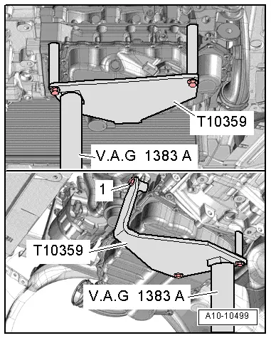
The engine is removed from underneath together with the gearbox.
t  All the cables, that are opened or cut during dismounting, should be placed again in the same location previously occupied during the fitting.
  Caution
Due to the enclosed spaces, observe the following during all assembly work, particularly in the engine compartment:
t  
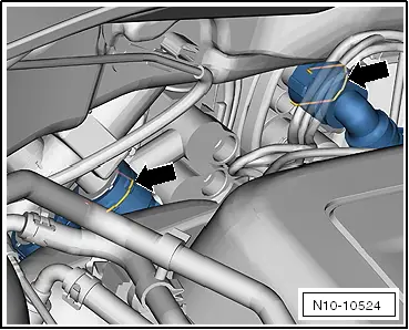
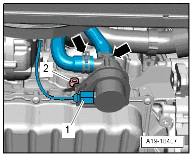
Route lines of any kind so that the original routing can be restored.
t  Ensure that there is sufficient clearance to all moving or hot components.
–  Interrogate fault memory of engine control unit → Vehicle diagnostic, testing and information system VAS 5051.
–  Disconnect earth strap at battery with ignition switched off → Electrical system; Rep. gr.27.
–  Remove engine cover → Chapter.
–  Remove the air filter housing → Chapter.
–  Remove battery → Electrical system; Rep. gr.27
   
–  Remove bolts -arrows- and take out battery mounting -1- .
–  Remove windscreen wiper arms → Electrical system; Rep. gr.92.
–  Remove the plenum chamber cover → Bodywork, exterior fitting work; Rep. gr.50.
  A27-10166
–  Pull off left engine wiring harness connector -arrow- from engine control unit.
  N10-10529
–  Pull out upper part upwards and remove engine wiring harness from cable guide.
  N10-10525
–  Remove cover for engine compartment electronics box. To do so, slide both catches in direction of -arrows-.
  A10-10349
–  Unscrew cable from alternator -A- and cable from battery -B- at fuse box.
  N10-10268
–  Unscrew earth cable from longitudinal member -arrow-.
  N10-10125
–  Open the catches of the cable guides on the longitudinal member -arrows-.
  A10-10563
–  Move clear and unplug electrical connector -1-.
–  Open wiring duct bracket located below -2-.
–  Remove wiring harness for engine control unit from wiring duct and place on engine.
–  Remove selector cable from gearbox → Power transmission; Rep. gr.34.
  A10-1576
–  Unplug electrical connector -2-.
  A27-10036
–  Loosen the top securing bolts of the air vent -arrows-.
  A19-0473
–  Release hose clip -2-.
–  Remove bolt -4-.
–  Disconnect electrical connector -arrow- and move wiring clear.
  WARNING
When the engine is warm, the cooling system is under pressure!
Hot steam/hot coolant can escape - risk of scalding.
Cover filler cap on coolant expansion tank with a cloth and open carefully to dissipate pressure.
–  Open filler cap on coolant expansion tank.
–  Remove the centre noise insulation → Bodywork, exterior installation work; Rep. gr.50.
–  Remove right wheel housing moulding → Bodywork, exterior installation work; Rep. gr.66.
  A21-10161
–  Remove charge air hoses -arrows-.
  N10-10090
–  Remove bolt -1- and take out air pipe downwards.
  A21-10161
–  Disconnect connector -1- and unscrew lower securing bolts -arrows- for air ducting.
–  Remove air vent downwards.
  Note
Collect drained coolant in a clean container for re-use or disposal.
–  Place drip tray for workshop cranes -VAS 6208- beneath engine.
–  Drain coolant → Chapter.
  A19-0473
–  Detach coolant hoses -1 and 2-.
  WARNING
The fuel line is under pressure!
Risk of injury to eyes and skin from fuel.
Wear safety goggles and protective clothing to avoid possible injury and skin contact. Before loosening hose connections, wrap a cloth around the connection. Then release pressure by carefully loosening the connection.
  A10-10257
–  Disconnect fuel supply pipe -1-.
–  Remove the air vent line -2-. To do this, press the quick-release coupling on the line and then »grasp« the lock and remove the quick-release coupling.
  N10-10584
–  Detach coolant hose at top of radiator -arrow-.
  A19-10406
–  Remove coolant hoses to heater heat exchanger -arrows-. Pull out retaining bar slightly to do this.
  N10-10524
–  Remove nuts (accessible from above) -arrows- securing front exhaust pipe to turbocharger.
  A26-10456
–  Pull off vacuum hoses -arrows-.
  Note
  N15-10705
Bolts of assembly mounting should only be loosened; do not unscrew more than 1 turn!
–  Loosen bolts -arrows- of assembly mounting on engine approx. 1 turn.
  A10-1898
–  Loosen bolts -arrows- of assembly mounting on gearbox approx. 1 turn.
  A10-1796
–  Remove the screws -1- and take off the heat shield for drive shaft on the right side.
–  Remove drive shafts → Running gear, axles, steering; Rep. gr.40.
–  Remove the primary exhaust pipe with catalytic converter → Chapter.
  Caution
Risk of breakage if the poly V-belt runs in the opposite direction when refitted.
Before removing, mark direction of operation of poly V-belt with chalk or felt-tipped pen in preparation for re-installation.
  N17-10184
–  To slacken poly V-belt turn tensioner from below in direction of -arrow-.
–  Secure tensioner with locking pin -T10060 A-.
–  Take out poly V-belt.
  N13-10338
–  Unplug the connector -1- for the air conditioning system compressor regulating valve -N280-.
  WARNING
Risk of injury due to refrigerant.
The air conditioning refrigerant circuit must not be opened.
–  Remove bolts -arrows- for air conditioner compressor.
  Caution
Risk of damage to refrigerant lines/hoses.
Do not stretch, kink or bend refrigerant pipes and hoses.
–  Tie up air conditioner compressor to longitudinal member with refrigerant hoses connected.
–  Remove the alternator -C- → Rep. gr.27.
  A10-1637
–  Remove bolt -2- at bracket for coolant pump for continued circulation -V51-.
  Note
The continued circulation coolant pump -V51- remains installed.
  A19-10407
–  Just loosen pendulum support on assembly mounting first then remove.
  N34-10973
–  Unplug electrical connector -1- for oil level and oil temperature sender -G266- and unclip bracket -2- from assembly carrier.
–  Disconnect all other electrical connections as necessary from engine/gearbox, and lay to one side.
–  Disconnect all connection, coolant, vacuum and intake hoses from engine.
  A10-10025
–  Attach engine bracket -T10359- to cylinder block by means of bolt -1-, tightening the bolt to 20 Nm.
  Note
Tapped hole for bolt -1- secures continued coolant circulation pump -V51-.
–  Insert engine and gearbox jack -V.A.G 1383 A- in engine bracket -T10359-.
–  Lift engine together with gearbox slightly.
  Note
To unscrew bolts for assembly mounting use stepladder -VAS 5085-.
  A10-10499
–  Remove bolts -arrows- of assembly mounting at engine.
  A10-1898
–  Unscrew securing bolts -arrows- of assembly mounting at gearbox.
  Note
t  Check that all hose and line connections between engine, gearbox and body have been detached.
t  Engine with gearbox must be guided carefully when lowered to prevent damage.
t  Note the selector lever cable.
–  Pull engine with gearbox as far forwards and to the left as possible, and then lower gradually.
Secure engine to engine and gearbox support -VAS 6095- to carry out repairs → Chapter.
  A10-1796

Disconnecting gearbox from engine and assembling > < Engine: Removing and installing