
Leon Mk1
| Crankshaft: disassembly and assembly |
 Note!
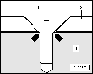
Note!| t | The cylinder block will be fitted with the correct thickness bearing shells at the factory. The thickness will be indicated using points of varying colours |
| t | For assembly, the engine must be secured to the -AR2204A- assembly stand with the -T20082- engine bracket. |

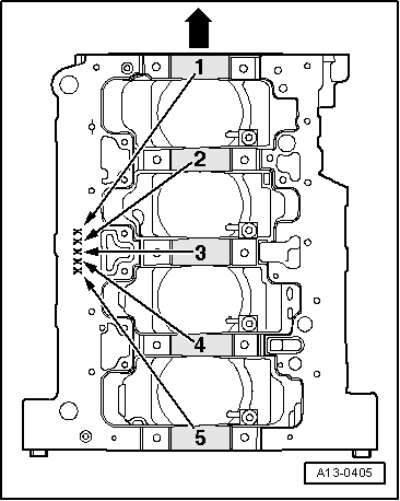
| 1 - | Half bearing 1, 2, 4 and 5 |
| q | For cylinder block with oil groove |
| q | Do not mix up used bearing shells (mark them) |
| q | Only use new half bearings that are marked with the same colours as those being replaced → Fig. |
| 2 - | Cog wheel for chain |
| q | For oil pump drive |
| 3 - | Half bearing |
| q | For bearing cap without oil groove |
| q | Do not mix up used bearing shells (mark them) |
| 4 - | Thrust washers |
| q | For cylinder block, bearing 3 |
| q | Note fixing arrangement |
| 5 - | 65 Nm + 1/4 turn (90°) |
| q | Replacement |
| q | Tighten to 65 Nm when measuring radial clearance |
| 6 - | Bearing caps |
| q | Bearing cap 1: pulley side |
| q | Bearing cap 3: with rebates for the thrust washers |
| q | Cylinder block bearing shell rims and bearing cap must coincide |
| 7 - | 10 Nm + 1/4 turn (90°) |
| q | Replacement |
| q | Each time that the bolts are loosened, the generator wheel must be replaced → Fig. |
| 8 - | Sender wheel |
| q | For engine speed sender -G28- |
| q | Can only be fitted in one position (the holes are offset) |
| q | Each time that the bolts are loosened, the generator wheel must be replaced |
| q | Removing and fitting → Fig. |
| 9 - | Crankshaft |
| q | Axial play: |
| q | new: 0,07 … 0,23 mm |
| q | Wear limit: 0,30 mm |
| q | Measure the radial play using a Plastigage |
| q | New: 0,02 … 0,04 mm |
| q | Wear limit: 0,15 mm |
| q | Do not rotate the crankshaft when checking the radial clearance |
| q | Do not rotate the crankshaft when checking the radial clearance |
| 10 - | Half bearing 3 |
| q | For cylinder block with oil groove |
| q | For bearing cap without oil groove |
| q | Do not mix up used bearing shells (mark them) |
| q | Only use new half bearings that are marked with the same colours as those being replaced → Fig. |
|
|
| Letters on the cylinder block | Colour of bearing shell | |
| S | = | black |
| R | = | red |
| G | = | yellow |
Note!
|