seat Workshop Repair Guides

SEAT Workshop Service and Repair Manuals

Assembly mountings > < Engine data
Engine: dismounting
   
Engine: dismounting
–  Detach engine cover -arrows-.
  E10-10017
–  In the versions with rigid battery protection, remove the cover -1-; press the release tab -arrow- to do so.
  WARNING
Note the precautionary instructions for disconnecting the battery → Electrical system; Rep. gr.27.
  A10-1611
–  With ignition switched off, disconnect earth wire -arrow- at battery.
  WARNING
Hot vapour/hot coolant may escape when opening expansion tank. Cover cap with cloth and open carefully.
–  Open cap on coolant expansion tank.
  A10-1612
–  Remove central soundproofing -Anchorage points 1 ... 3-.
  A10-1565
–  Remove left and right noise insulation -1- on coolant outlet temperature sender -G2-.
–  Place the drip tray -T20173- under the engine.
For engines with identification letters BLR and BLY
–  Turn drain plug -arrow- on radiator anti-clockwise, if necessary fit drain hose to connection.
–  Pull off bottom coolant hose retaining clip and remove hose -2- from radiator.
  A10-1568
For engines with identification letters BVY and BVZ
Release the quick connection -arrow-, and remove the coolant hose from the radiator.
  N19-0276
Continue for all engines
–  Disconnect the connector -1- of the oil pressure sender -F1-.
–  Additionally take coolant hose on lower part of oil cooler off -2- and drain off remaining coolant.
  A19-0391
–  Remove the air intake hose -arrow- at the bottom at the resonance pipe. To do this, release the spring clamp using the counterhold -T20174- and bolt-1-.
  E10-10018
–  Remove the flexible tube -1- from the air filter housing.
–  Disconnect the connector -2- in the air filter housing.
–  Remove bolt -3-.
–  Disconnect the air hose -4- from throttle valve module. To do this, release the spring clamp using the counterhold -T20174-.
–  Take out air cleaner housing.
–  Remove air intake hose to the resonator from the lock carrier and take it out.
–  Remove battery → Electrical system; Rep. gr.27.
  A10-1613
–  Remove battery tray -arrows-.
–  Detach battery tray from air duct at front.
  A10-1572
–  Pull rubber seal -2- off plenum chamber cover.
  E92-10015
–  Remove bolts -1-.
–  Unhook the rear engine wiring harness on the parting wall for plenum chamber.
  E92-10014
–  Remove parting wall for plenum chamber -arrows-.
  A10-1573
–  Remove engine control unit → Chapter.
–  Disconnect electrical connection -1- and -2- from engine wiring harness.
  A24-0730
–  Release the engine wiring harness guide -arrow- and pull out upwards.
  A10-1574
–  Remove the connectors -1- and -2- of the lambda probes in front of the catalytic converter of the support and disconnect them. (The number of connectors may vary depending on version).
  A10-1614
–  Open cable guide retainer -arrows-.
  A10-1575
–  Unlock connector -1- and separate.
  A10-1576
–  Release and unplug connector -1-.
–  Open the support -2- of the cable guide beneath.
–  Open the cable guide support -3-.
–  Take the engine wiring harness to the control unit out of the cable guide.
  A10-1615
–  Unplug electrical connector -4- for reversing light switch.
–  Unscrew earth connection -3-.
–  Disconnect the connector -1- in the starter motor.
–  Unbolt the connector -2- in the starter motor.
–  Uncover cables.
  A27-0204
–  Remove the cover on the fusebox, by pressing release tab -arrows-.
  A10-1624
–  Remove the cable -arrow- and lay bare as far as the alternator and the air conditioner compressor.
  A10-1735
–  Remove the coolant hose from the dash panel plate -1-.
–  Remove the coolant hoses that go to the heat exchanger -2- and -3-.
  A10-1616
–  Pull vacuum hose -3- off the brake servo on the intake pipe.
–  Remove coolant hose -1-.
–  In vehicles with engine code BLR and BLY, remove the coolant hose -2- towards throttle valve control unit.
  A10-1619
–  Disconnect the coolant hose from the upper part of the radiator -arrow-.
  A10-1617
–  Remove coolant hose -arrow-.
  A10-1618
Vehicles with manual gearboxes
–  Unclip securing clips -1- and -2- on both control cables.
–  Pull off selector cable support elements from gearbox selector lever and relay lever.
–  Remove cable support bracket from gearbox and lay to side -arrows-.
  A10-1631
–  Remove strut -1-.
–  Remove clutch slave cylinder -arrows- and place to one side; do not disconnect pipe.
  WARNING
Do not depress clutch pedal after removing slave cylinder.
Vehicles with automatic gearbox
–  Separate the gearbox cables → 6-speed automatic gearbox 09G; Rep. gr.37.
  A10-1630
Continued for all vehicles
–  Disconnect the coolant hoses -1- and -2- in the expansion tank.
  WARNING
Fuel system is under pressure! Before opening the system place a cloth around the connection. Then release pressure by carefully pulling fuel hose from connection. Wear eye protection and gloves to avoid injuries and skin contact.
  A10-1621
–  Disconnect the hose to the active carbon filter -1-.
–  Remove the fuel supply tube -2-.
  E10-10020
–  Disconnect the vacuum pipe -1- to the active carbon filter (by pressing the release tab).
  E10-10019
–  Take the active carbon filter out upwards with connected hoses -arrow-.
  A10-1581
–  Release the coolant hose bracket on the right-hand longitudinal member -arrow-.
  Note
  A10-1740
Before removing the ribbed belt, mark its running direction with chalk or with a felt tipped pen. Running a used belt in the opposite direction could destroy it.
–  To slacken off poly V-belt, swivel belt tensioner in -direction of arrow-.
–  Remove the ribbed belt.
  A13-0083
–  Unscrew bolts -arrows- Equipment mounting, engine side, approx. 2 turns.
  A10-1642
–  Unscrew the securing bolts -arrows- of the engine assembly, gearbox side by approx. 2 rotations.
  A10-1634
–  Disconnect connector -1-.
–  Open the cableguide clips -2- and -3- and lay the cables bare.
–  Place the lock carrier plate into service position →  Bodywork, exterior fitting work ; Rep. gr.50
  WARNING
The air conditioning refrigerant circuit must not be opened.
–  Remove left wheel housing moulding → Bodywork, exterior fitting work; Rep. gr.66.
  A10-1625
–  Disconnect electrical connection -1- for electromagnetic coupling on air conditioner compressor.
–  Unscrew the bolts -arrow- for air conditioner compressor.
  Note
To avoid damage to the air conditioning compressor or in the flexible conduits/tubes of the cooling agent, the tubes must not be pulled, bent or stretched excessively.
–  Fasten the air conditioning compressor and the coolant hoses to the lock carrier.
  A10-1637
–  Disconnect connector -1-.
–  Remove the electric fan together with the radiator cowl. Remove bolts -arrows- on both sides for this purpose.
  A10-1627
–  Remove coolant hose -2-, pull out retaining clip -1- for this purpose.
  A10-1736
–  Remove right vehicle floor cover -arrows-.
  Note
  A10-1663
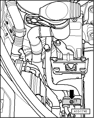
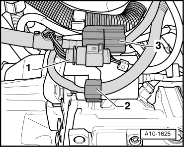
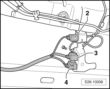
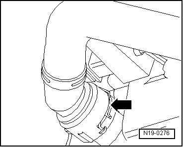
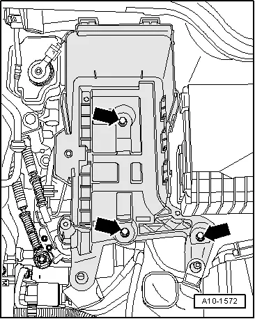
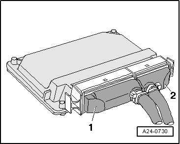
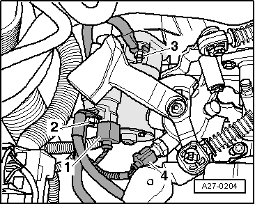
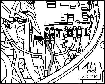
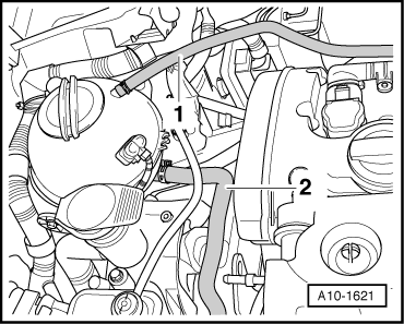
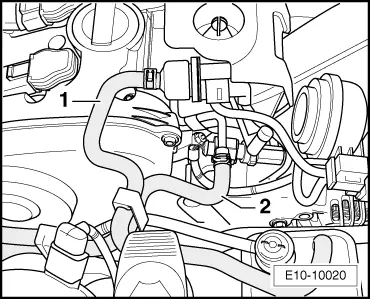
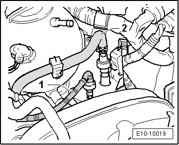
Before detaching the connectors of the lamda probes, mark the pairs, to avoid exchanging parts when reassembling ( the following diagram shows the position of the connectors for engine code BLR).
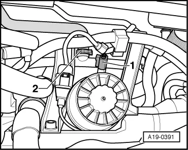
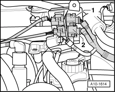
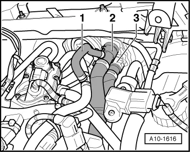
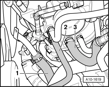
–  Detach the connector (grey) -2- for lambda probe III behind the catalyser -G287- with heating of lamda probe 3, behind the catalyser -Z64- and leave the cable bare.
–  Detach the connector (brown) -3- for lambda probe behind the catalyser -G130- with heating of lamda probe 1, behind the catalyser -Z29- and leave the cable bare.
–  Detach the connector (black) -4- for lamda probe II behind the catalyser -G131- with heating of lamda probe 2, behind the catalyser -Z30- and expose the cable.
  E26-10008
–  Remove the front cross member from the underbody -arrows-.
  Note
The vibration shock absorbing elements in the front exhaust pipe must not be bent more than 10° - otherwise they can be damaged.
  E10-10016
–  Remove exhaust system from double clamp -arrows-.
  A10-1734
–  Unbolt the exhaust system bracket -arrows-.
  A10-1632
–  Unbolt heat shield for right drive shaft -arrows-.
  A10-1633
–  Remove securing nuts -arrows- for exhaust manifold to front exhaust pipe.
–  Take exhaust pipe off with catalytic converter.
–  Unbolt the drive shaft from the gearbox flange, to left and right → Running gear - Front wheel drive and 4WD; Rep. gr.40.
–  Fasten the left-hand drive shaft in a high position.
  WARNING
To loosen the combi bolt for drive shaft, the wheel bearing must not be loaded (the vehicle must not stand on the wheels).
  N10-10085
–  Undo the combi bolt -2- on the right-hand drive shaft. To prevent rotation pump the brake (a second mechanic is necessary).
–  Remove both front wheels.
  A40-0444
–  Unscrew the bolts crossways -1 ... 3- and remove the pendulum support.
–  Dismount the right-hand drive shaft using the extractor -T20001A-. In order to separate the drive shaft it may be necessary to move the engine assembly in the opposite direction to the direction of travel.
  A10-1578
–  Pull connector -1- out of bracket and set wiring aside.
–  Unscrew the bolts crossways -2 ... 4-.
  A10-1749
–  Bring the securing tool -T20205- with the hydraulic jack -SAT 1040- and turn the bolt -4- until it is parallel with the engine block.
–  From the rear of the engine -A-, first insert the fixed column -1-, then adjust the mobile column -2- as necessary and then screw on the nuts -arrows-.
–  From the front of the engine -B-, position the mobile column -6- and adjust the bolt -5-.
–  Adjust the bolt -3- to immobilise the securing tool -T20205-.
  Note
To unscrew the bolts for gearbox mounting use the step ladder.
  E10-10043
–  Unscrew the bolts -arrows- of the gearbox/engine mounting...
  A10-1642
–  Release the securing bolts -arrows- of the engine assembly, gearbox side.
  Note
t  Check that all hoses and other connections between engine, gearbox and body have been detached.
t  To avoid damage, guide the engine/gearbox mounting carefully when lowering.
–  Pull engine/gearbox assembly as far as possible forwards and lower it slowly downwards.
  A10-1634

Assembly mountings > < Engine data