
Leon Mk1
|
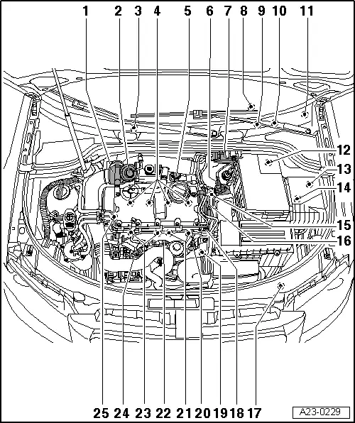
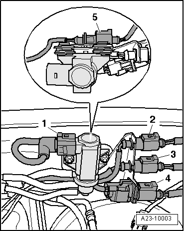
| 1 - | Intake manifold flap motor -V157- |
| q | Removing and installing → Chapter |
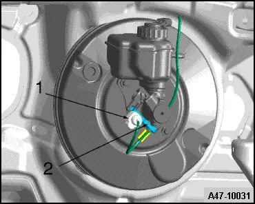
| 2 - | Mechanical exhaust-gas recirculation valve |
| 3 - | Engine control unit |
| q | Replace → Chapter |
| 4 - | Injector pump units |
| q | Valve for injector pump, cylinder 1 -N240- |
| q | Valve for injector pump, cylinder 2 -N241- |
| q | Valve for injector pump, cylinder 3 -N242- |
| q | Valve for injector pump, cylinder 4 -N243- |
| q | Removing and installing → Chapter |
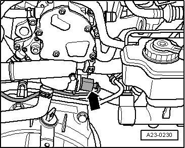
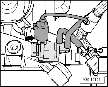
| 5 - | Exhaust gas recirculation change over valve |
| q | With vehicles with engine code letters BKC, BXE, BXF |
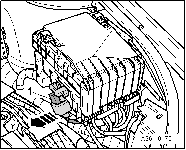
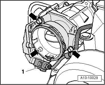
| 6 - | Air mass meter -G70- |
| q | Removing and installing → Chapter |
| 7 - | Solenoid valve block |
| q | With exhaust gas recirculation valve 1 -N18- |
| q | With solenoid valve for the supercharger pressure limitation -N75- |
| q | With Exhaust gas recirculation radiator change over valve -N345- |
| 8 - | Engine electronics pilot light -K149- |
| q | On the instrument panel |
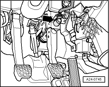
| 9 - | Accelerator pedal position sender -G79- and accelerator pedal position sender -2 -G185- |
| q | Fitting location → Fig. |
| q | Removing and installing → Chapter |
| 10 - | Brake light switch -F- and brake pedal switch -F63- |
| q | It is located on the brake pump. |
| 11 - | Fuel pump fuse: -J17- |
| q | Fitting location → Current flow diagrams, Electrical fault finding and Fitting locations |
| 12 - | Clutch position sender -G476- |
| 13 - | Relay carrier and fuse holder in the engine compartment electrics box |
| q | With voltage supply relay terminal 30 -J317- |
| q | With voltage supply relay terminal 15 -J329- |
| q | Fitting location → Current flow diagrams, Electrical fault finding and Fitting locations |
| 14 - | 6 element relay carrier |
| q | Underneath the electrics box (E-Box) in the engine compartment |
| q | with control unit for automatic control of glow time -J179- |
| q | Fitting location → Current flow diagrams, Electrical fault finding and Fitting locations |
| 15 - | Coolant temperature sender -G62- |
| q | Fitting location → Fig. |
| q | Before removing release pressure in cooling system, if necessary. |
| 16 - | Tandem pump: |
| q | Removing and installing → Chapter |
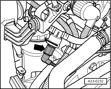
| 17 - | Coolant temperature sender -G83- |
| q | Fitting location → Fig. |
| 18 - | Multiple connector |
| q | For the injector pump |
| q | Fitting location → Fig. |
| 19 - | Engine speed sender -G28- |
| q | Fitting location → Fig. |
| q | Removing and installing → Chapter |
| 20 - | Fuel temperature sensor -G81- |
| q | Fitting location → Fig. |
| 21 - | Glow plugs |
| q | Glow plug 3 -Q12- |
| q | Glow plug 4 -Q13- |
| q | Removing and installing → Chapter |
| 22 - | 3-pin connector |
| q | for Hall sender -G40- |
| q | Fitting location → Fig. |
| 23 - | Glow plugs |
| q | Glow plug 1 -Q10- |
| q | Glow plug 2 -Q11- |
| q | Removing and installing → Chapter |
| 24 - | Supercharger pressure sender -G31- with Intake air temperature sender -G42- |
| q | Fitting location → Fig. |
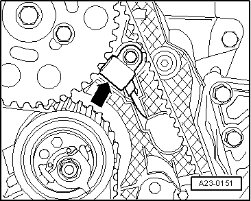
| 25 - | Hall sender -G40- |
| q | For camshaft position. |
| q | Fitting location → Fig. |
|
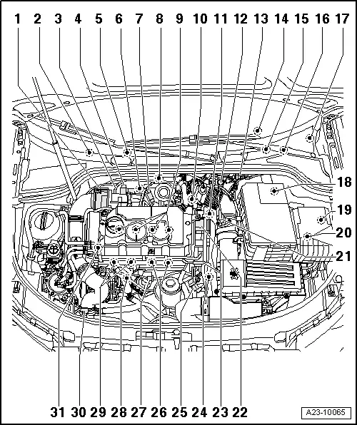
| 1 - | Intake manifold flap motor -V157- |
| q | Removing and installing → Chapter |
| 2 - | Temperature sensor behind particle filter -G527- |
| q | Fitting location → Fig. |
| q | Removing and installing → Chapter |
| 3 - | Lambda probe -G39- withheater for the lambda probe -Z19- |
| q | Fitting location → Fig. |
| q | Removing and installing → Chapter |
| 4 - | Exhaust gas recirculation valve -N18- with potentiometer for exhaust gas recirculation -G212- |
| q | Fitting location → Fig. |
| 5 - | Engine control unit |
| q | Removing and installing → Chapter |
| 6 - | Exhaust gas temperature sender 2, bedplate 1 -G448- |
| q | Fitting location → Fig. |
| q | Removing and installing → Chapter |
| 7 - | Pressure sensor 1 of exhaust gases -G450- |
| q | Fitting location → Fig. |
| q | Removing and installing → Chapter |
| 8 - | Exhaust gas temperature sender 1 -G235- |
| q | Fitting location → Fig. |
| q | Removing and installing → Chapter |
| 9 - | Injector pump units |
| q | Valve for injector pump, cylinder 1 -N240- |
| q | Valve for injector pump, cylinder 2 -N241- |
| q | Valve for injector pump, cylinder 3 -N242- |
| q | Valve for injector pump, cylinder 4 -N243- |
| q | Removing and installing → Chapter |
| 10 - | Exhaust gas recirculation radiator change-over valve -N345- |
| q | Fitting location → Fig. |
| 11 - | Coolant temperature sender -G62- |
| q | Fitting location → Fig. |
| q | Before removing, reduce cooling system pressure if necessary |
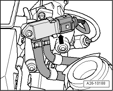
| 12 - | Charge pressure control solenoid valve -N75- |
| q | Fitting location → Fig. |
| 13 - | Connectors on the left of the dashboard. |
| q | Fitting location → Fig. |
| 14 - | Engine electronics pilot light -K149- |
| q | On the instrument panel |
| 15 - | Accelerator pedal position sensor -G79- with accelerator pedal position sensor 2 -G185- |
| q | Fitting location → Fig. |
| q | Removing and installing → Chapter |
| 16 - | Brake light switch -F- and brake pedal switch -F63- |
| q | Fitting location → Fig. |
| 17 - | Fuel pump fuse: -J17- |
| q | Fitting location → Current flow diagrams, Electrical fault finding and Fitting locations |
| 18 - | Clutch position sender -G476- |
| 19 - | Electronics box relay carrier and fuse box in the engine compartment |
| q | With voltage supply relay terminal 30 -J317- |
| q | With voltage supply relay terminal 15 -J329- |
| q | Terminal plug → Current flow diagrams, Electrical fault finding and Fitting locations |
| 20 - | Control Unit of the automatic preheating cycle -J179- |
| q | Underneath the electrics box (E-Box) in the engine compartment |
| q | Fitting location → Fig. |
| 21 - | Air mass meter -G70- |
| q | Removing and installing → Chapter |
| 22 - | Tandem pump: |
| q | Removing and installing → Chapter |
| 23 - | Multiple connector |
| q | For the injector pump |
| q | Fitting location → Fig. |
| 24 - | Engine speed sender -G28- |
| q | Fitting location → Fig. |
| q | removing and fitting → Chapter |
| 25 - | Fuel temperature sensor -G81- |
| q | Fitting location → Fig. |
| 26 - | Glow plugs |
| q | Glow plug 3 -Q12- |
| q | Glow plug 4 -Q13- |
| q | Removing and installing → Chapter |
| 27 - | 3-pin connector |
| q | for Hall sender -G40- |
| q | Fitting location → Fig. |
| 28 - | Radiator outlet coolant temperature sender -G83- |
| q | Fitting location → Fig. |
| 29 - | Glow plugs |
| q | Glow plug 1 -Q10- |
| q | Glow plug 2 -Q11- |
| q | Removing and installing → Chapter |
| 30 - | Supercharger pressure sensor -G31-/intake air temperature sensor -G42-. |
| q | Fitting location → Fig. |
| 31 - | Hall sender -G40- |
| q | For camshaft position. |
| q | Fitting location → Fig. |
|
|
 Note
Note
Note
|
|
|
|
|
|
|
|
|
|
Note
|
|
|

|
|
|
Note
|
|
Note
|
|
|
|
|
|
|
|
|
|
|
|
|
|
|
|
|
|