
Leon Mk1
|
|
|
|
|
|
|
 Note
Note
|
|
|
|
|
|
|
|
|
|
|
|
|
|
|
|
|
|
|
|
Note
|
|
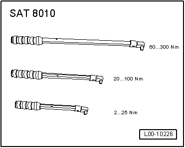
| Component | Nm | |
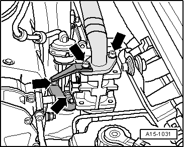
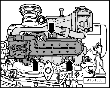
| Exhaust gas recirculation system radiator to bracket | 10 | |
| Exhaust gas recirculation connecting pipe to exhaust manifold | 22 → Remark | |
| Exhaust gas recirculation connecting pipe to exhaust gas recirculation radiator | 22 → Remark | |
| Air hose (rear) to bracket | 10 | |
|