
Leon Mk1
|
| Consult the equivalence table for tools and equipment according to applicability among Seat / VW / Audi / Skoda → Chapter. |

| Special tools and workshop equipment required |
| t | Socket wrench 22 mm -T20202A-, see equivalent → Anchor |
| t | Socket wrench 17 mm -T20211-, see equivalent → Anchor |
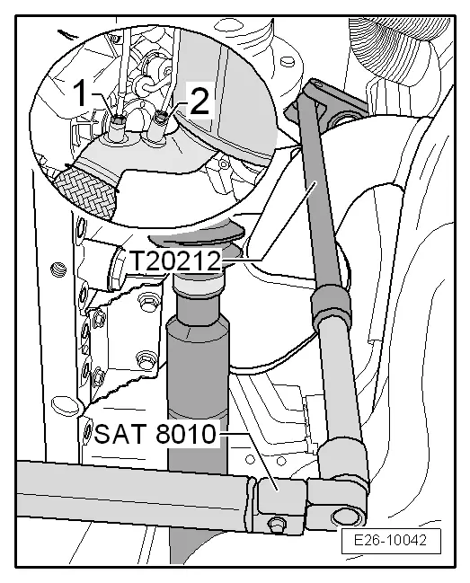
| t | Articulated wrench e/c 17 -T20212-, see equivalent → Anchor |
| t | "Ratchet 1/2"" x 9-12" -VAG 1331/1-, see equivalent → Anchor |
| Special tools and workshop equipment required |
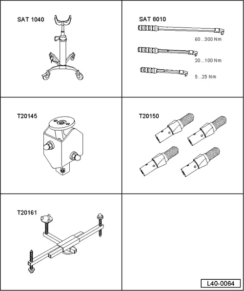
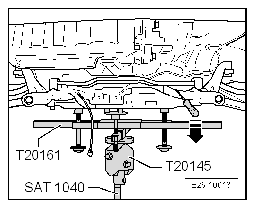
| t | Hydraulic jack -SAT 1040-, see equivalent → Anchor |
| t | Torque wrench kit -SAT 8010-, see equivalent → Anchor |
| t | base -T20145-, see equivalent → Anchor |
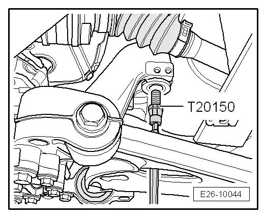
| t | Centre guide -T20150-, see equivalent → Anchor |
| t | counterhold -T20161-, see equivalent → Anchor |
|
|
 Note
Note
|
|
Note
|
|
|
|
|
|
|
|
|
|
|
|
|
|
|
|
|
|
|
|
Note
|
|
|
|
|
|
|
|
|
|
|
|
|
|
|
|
Note |
|
|
|
Note
|
|
|
|
Note
|
|
Note
|
|
Note
|
|
| Component | Nm | ||||
| Exhaust bracket to subframe | 23 | ||||
| Tube before turbocharger exhaust | 7 | ||||
| Particle filter support to particle filter | 23 | ||||
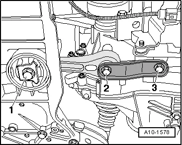
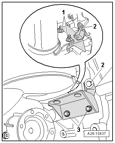
| Pendulum support to gearbox | 40 + 90° 1)2) | ||||
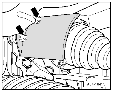
| Heat shield to cylinder block | 35 | ||||
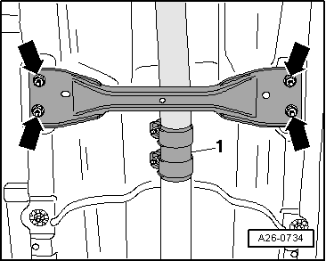
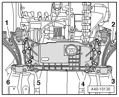
| Front crosspiece of the vehicle to the bodywork | 23 | ||||
| Pressure tube to particle filter | 40 | ||||
| |||||