seat Workshop Repair Guides

SEAT Workshop Service and Repair Manuals

Control unit with anti-theft protection, version 2: Removing and installing. > < Control unit with anti-theft system: removing and fitting
Control unit with anti-theft protection, version 1: Removing and installing.
If you wish to renew the engine control unit, connect the → Vehicle diagnostic tester and carry out the guided function „Renew control unit“.
t  Removing → Anchor
t  Install → Anchor.
Consult the equivalence table for tools and equipment according to applicability among Seat / VW / Audi / Skoda → Chapter.
Special tools and workshop equipment required
   
t  Plate work saw -VAG 1523B-, see equivalent → Anchor
t  Hot air gun from cable repair set -VAS 1978A-, see equivalent → Anchor
Removing
–  Switch off ignition and remove key.
–  Remove the front panel of the plenum chamber → Bodywork, exterior fitting work; Rep. gr.50.
–  Take engine control unit out of retainer.
  W00-0005
Using the body saw -VAG 1523B- make a groove on the heads of the shear screws for inserting a screwdriver.
  Note
t  The groove must be wide enough in order to be able to screw out the screws using an appropriate screwdriver.
t  The thread on the shear screws can been treated with a threadlocker. For making sure that unscrewing is easier, you can warm the shear screws using the Hot air blower -VAS 1978/14A-. In doing so, take care that no bordering cables, connectors or components are damaged! .
  WARNING
The threads of the two shear screws which are screwed into the engine control unit are not secured with locking fluid. Do not apply heat to the threads in the control unit housing; this is not necessary and would cause overheating of the control unit.
The threads of the two shear screws which are screwed into the engine control unit are not secured with locking fluid. To unscrew these bolts, the threads must therefore be heated with the hot-air blower.
To ensure that damage (burning) is not caused to the cables and connectors as well as insulation and control units, the following steps must be observed in all cases: Remember the instructions for using the hot-air gun.
Carry out the adjustments on the hot air blower -4- as described below:
  S24-0705
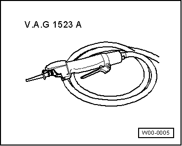
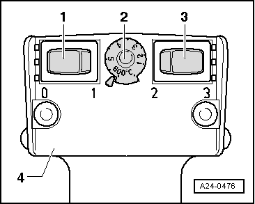
–  Turn temperature setting potentiometer -2- to maximum heat output (600°C).
–  Set the two-level switch for air flow -3- to position 3.
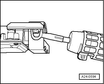
  WARNING
The threads of the two shear screws which are screwed into the engine control unit are not secured with locking fluid. Do not apply heat to the threads in the control unit housing; this is not necessary and would cause overheating of the control unit.
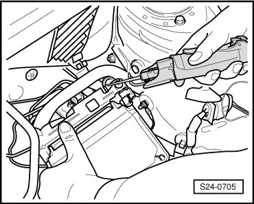
When breakaway bolts are heated, some parts of the protective casing become very hot. Risk of burn injuries! Also, make sure that, as far as possible, you only heat the breakaway bolt and not adjoining parts. If necessary, cover these parts.
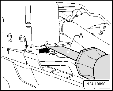
  Note
Next, heat the breakaway bolts with the hot-air gun. This reduces the strength of the threadlocker on the thread of the breakaway bolts to make them easier to remove.
  A24-0476
–  Bring the nozzle of the hot-air gun up to the breakaway bolt on the lock.
–  Connect hot air gun and heat the head bolt approx. 20 to 25 seconds.
  A24-0594
–  Unscrew the shear screws using a screwdriver.
  E23-10022
–  Insert a screwdriver -A- between the protective cover and the retention plate -arrow-.
  N24-10098
–  Lift the protective cover by levering it with a screwdriver -A-, and remove it from the retention plate sideways -arrow-.
  N24-10097
–  Release and unplug front connector -1- on engine control unit.
–  Prise out outer frame -2- a little.
–  Then remove the engine control unit from the support -arrow-.
–  Release and unplug the rear connector on engine control unit.
Installing
–  Remove the remains of the threadlocker from the breakaway bolt holes. A male thread tap can be used for this.
–  Attach rear connector to the engine control unit and lock connector.
–  Fit the engine control unit onto the retention plate.
–  Now connect the front connector to the engine control unit and lock.
–  Mount the protective cover on the retention plate.
–  Use new breakaway bolts.
  N24-10056
–  Tighten the breakaway bolts -1- evenly until they break.
–  Install the front panel of the plenum chamber → bodywork, exterior fitting work; Rep. gr.50.
When replacing the engine control unit
–  Adjust the new engine control unit.
–  Read fault memory, repair faults if necessary and then clear fault memory → Vehicle diagnostic tester„Guided fault finding“.
–  If the fault memory has been erased, you must generate the readiness code again.
–  Take vehicle for a test drive.
–  Read control unit fault memory again.
  N24-10055

Control unit with anti-theft protection, version 2: Removing and installing. > < Control unit with anti-theft system: removing and fitting