seat Workshop Repair Guides

SEAT Workshop Service and Repair Manuals

Valve control: repairs > < Intake manifold: removing and fitting
Cylinder head: fitting
  WARNING
When doing any repair work, especially in the engine compartment, pay attention to the following due to the cramped conditions:
t  Route all the various lines (e.g. for fuel, hydraulics, active carbon filter system, coolant, refrigerant, brake fluid and vacuum pipes and hoses) and electrical wiring so that the original positions are restored.
t  
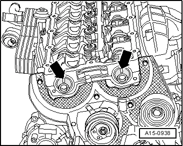
Ensure that there is sufficient clearance to all moving or hot components.
  Note
t  Carefully remove any remains of sealant from the cylinder head and cylinder block. Ensure that no scoring or scratching is produced.
t  Carefully remove any remaining emery and abrasive material.
t  No oil or coolant must be allowed to remain in the blind holes for the cylinder head bolts in the cylinder block.
t  
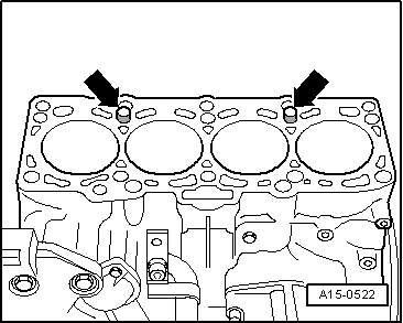
Renew cylinder head bolts.
t  When fitting, replace the self-locking nuts and bolts.
t  Renew bolts which have a specified tightening angle, as well as seals and gaskets.
t  
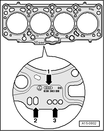
Do not remove the new gasket from its packaging until just before fitting.
t  Handle gasket extremely carefully. Damaging the silicone layer or the indented area will lead to leaks.
t  When fitting a new cylinder head with the camshafts fitted, the contact surfaces between the roller rocker arms and the cam contact surfaces must be oiled following the fitting of the cylinder head.
t  The plastic protectors fitted to protect the open valves should not be removed until the cylinder head is ready to be fitted.
t  Secure all hose connections with the correct hose clips (same as original equipment) → Parts catalogue.
   
–  Check if the camshaft and the crankshaft are in TDC:
l  The grooves -arrows- for the valve cotters should point upwards.
  A15-0938
l  The crankshaft toothed belt pinion should be immobilised with the Retaining tool -T10050- for engines with round pinion for the crankshaft toothed belt or with the Retaining tool -T10100- for engines with oval pinion for the crankshaft toothed belt.
  Note
The marks in the toothed belt pinion and in the Retaining tool should be aligned -arrow-.
  N15-10159
–  Note the cylinder head identification.
t  Part No. = -Arrow 1-
t  Production code = -Arrow 2- (can be disregarded)
t  Holes = -Arrow 3-
  Note
t  If the gasket or the cylinder head is replaced, fit a new gasket with the same identification.
t  If components of the crankshaft mechanism are replaced, the new gasket must be selected by measuring the projection of the pistons at TDC.
  A15-0802
–  Assemble the cylinder head gasket with the mark facing upwards.
l  Note the dowel sleeves -arrows- on the engine block.
l  Note the fitting position of the cylinder head; the marking “oben” (up) or the part number should face the cylinder head.
Vehicles equipped with small engine support foot
–  Place the cylinder head onto the cylinder block.
  A15-0522
Vehicles equipped with large engine support foot
–  Place the retaining tool -T20127- in the cylinder head joint supports and in the shop crane, as shown in the figure.
  DANGER!
Ensure that the hooks are closed with the security rings.
–  Raise a little the cylinder head with the shop crane.
–  Turn the cylinder head with the toothed belt tension roller threaded bolt in the rebate of the toothed belt rear protector and at the same time place the tension roller.
–  Place the cylinder head onto the cylinder block.
  E10-0109
All vehicles (continued):
–  Insert cylinder head bolts and tighten by hand.
–  Tighten the cylinder head in 4 stages, in the following tightening sequence:
  A15-0939
stage:Tighten
I
–  Tighten using the torque wrench to 40 Nm.
II
–  Tighten using the torque wrench to 60 Nm.
III
–  Turn further with rigid spanner 90° (1/4 turn).
IV
–  Turn further with rigid spanner 90° (1/4 turn).

  Note
Cylinder head bolts do not have to be torqued down again later after repair work.
   
–  Fasten the timing belt rear protection to the cylinder head
–  Use locking fluid for the bolts -2 … 5-.
t  Locking fluid → Parts catalogue
–  Tighten the threaded pin -1-
  A15-0934
–  Check if the camshaft and the crankshaft are in TDC:
The grooves -arrows- for the valve cotters should point upwards.
–  Fit the tensioning roller and fasten with bolt.
  Note
  A15-0938
Ensure that tensioning roller is seated properly in rear timing belt guard -arrow-.
–  Assemble the camshaft wheels and hubs.
–  Immobilise the hubs using the retention tools -T20102-.
  A13-0053
Vehicles with round wheel for the crankshaft timing belt
–  Immobilise the crankshaft notched belt wheel using the retention tool -T10050-.
  A13-0350
Vehicles with an oval wheel for the crankshaft timing belt
–  Immobilise the crankshaft timing belt wheel using the counterhold -T10100-.
  A13-10235
–  Before fitting the rocker arm shaft, check if all of spherical head pins -1- and the O-rings -2- are fitted on the injector pump units.
  A15-0942
–  Tighten the rocker arm shaft as shown below:
  A15-0936
SequenceTighten
I
–  Tighten the bolts -2- and -4- alternately in stages until the rocker arm shaft sits on the bearing cap module.
II
–  Also tighten the bearing caps -1-, -3- and -5- to the torque of 20 Nm + 90° (1/4 turn).
III
–  Tighten the bolts -2- and -4- to 20 Nm + 90° (1/4 turn).
IV
–  Tighten the bolts -6 ... 10- with 20 Nm.

   
–  Fit the hub to the exhaust camshaft.
–  Tighten securing bolt -1- to 100 Nm (use counter holder -T10051-).
  A15-0931
–  Fit the hub to the supply camshaft.
–  Tighten securing bolt -1- to 100 Nm (use counter holder -T10051-).
  A15-0930
–  Move the camshaft wheels to the hubs.
l  The notched section -arrows- of the camshaft wheels must face up.
–  Screw in the bolts -1- without tightening.
–  Immobilise the hubs using the retention tools -T20102-.
The remaining installation steps are carried out in reverse sequence - note the following points:
–  Install the toothed belt (adjusting valve timing): vehicles with small engine support → Anchor; vehicles with large engine support → Anchor
–  Fit the cylinder head: vehicles with engine codes AZV, BKD → Chapter, vehicles with engine codes BMN → Chapter
–  Install vibration damper → Chapter.
–  Install poly V-belt → Chapter.
Vehicles with engine codes AZV, BKD:
–  Install front exhaust pipe → Chapter.
Vehicles with engine codes BMN,
–  Mount the right half-shaft → Rep. Gr.40
–  Mount the particle filter → Chapter.
All vehicles (continued):
–  Install exhaust system and align it free of stress → Chapter.
–  Mount the left half-shaft → Rep. Gr.40.
–  Connect battery. Precautions → Electrical system; Rep. Gr.27.
–  Check oil level . → Chapter.
  Note
Carry out an engine oil change if this is dirty → Booklet101.
–  Fill up coolant → Chapter.
Tightening torques
  E15-10005
ComponentNm
Rocker arm shaft to cylinder head20 + 90° → Note → Note
Bearing cap module to cylinder head20
Notched belt rear protection to cylinder head10 → Note
Hall sender to the cylinder head10 → Note
Pin to cylinder head15
Hubs to the camshafts100
Oil pressure switch to oil filter bracket20
Oil supply pipe to the turbocharger22
Oil supply pipe to oil filter bracket22
Oil return pipe to the engine block30
Bracketto turbocharger20
TurbochargerTo engine block40
Pendulum support to subframe100 + 90° → Note → Note
Front supercharger air tube to the engine block22

1)  Replace bolts
2)  90º is equivalent to a quarter turn
3)  Fit with locking fluid; locking fluid → Parts catalogue
   

Valve control: repairs > < Intake manifold: removing and fitting