seat Workshop Repair Guides

SEAT Workshop Service and Repair Manuals

Central diagnosis systemVAS 505X : connect and select functions > < ABS system components on the front axle: removing and fitting
Control unit and hydraulic unit: removing
   
Control unit and hydraulic unit: removing
Special tools and workshop equipment required
t  Torque wrench -V.A.G 1331-
t  Torque wrench -V.A.G 1410-
t  Brake pedal depressor -V.A.G 1869/2-

   
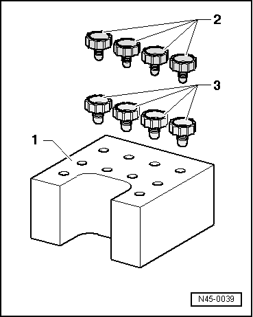
Sealing plug repair kit, Part no. 1H0 698 311 A
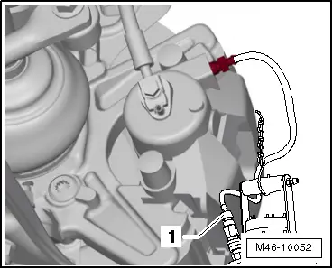
1 - Transport protection for valve domes (foam)
2 - M 10 seal bolt
3 - M 12 seal bolt
Removal:
Installation location:
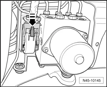
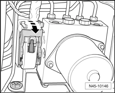
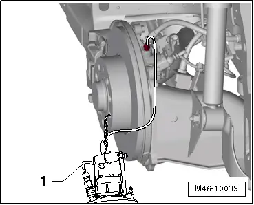
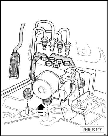
The control unit is bolted to the hydraulic unit and is located on left in the engine compartment, under the battery tray.
  WARNING
Do not bend the brake lines in the vicinity of the hydraulic unit.
–  Check and note the code for the control unit fitted.
–  Note or request radio code on vehicles with coded radio if necessary.
–  Disconnect battery → Electrical system; Rep. gr.27.
–  Remove air intake hose, air filter housing and battery. → Electrical system; Rep. gr.27
–  Remove battery tray.
–  Open cable duct, take out the two wiring harnesses and place on one side.
–  Remove cable duct from console.
  N45-0039
–  Press red locking slide downwards in direction of -arrow-.
  N45-10145
–  Release connector from control unit in direction of -arrow- and pull off.
  N45-10146
–  Set up brake pedal actuator -V.A.G 1869/2-.
  A44-0007
–  Attach the breather hose of the bleeding bottle -1- onto the breather valve of the brake calliper front left.
–  Open the bleeder valve.
  M46-10052
–  Attach the breather hose of the bleeding bottle -1- onto the breather valve of the brake calliper rear left.
–  Open the bleeder valve.
–  Depress brake pedal at least 60 mm using brake pedal depressor -V.A.G 1869/2-.
–  Close the front and rear left bleeding screws.
–  Do not remove brake pedal depressor -V.A.G 1869/2-.
–  Place a sufficiently large lint-free cloth under the ABS hydraulic unit -N55-.
Make sure that brake fluid does not fall onto the connectors.
–  First identify both brake lines from brake master cylinder and then remove.
–  Immediately seal brake lines and threaded holes with seal plugs from repair set Part No. 1H0 698 311 A.
–  Mark, unscrew and seal remaining brake lines (brake calipers).
  M46-10039
–  Pull hydraulic unit together with control unit upwards out of dampers -arrow-.
  N45-10147

Central diagnosis systemVAS 505X : connect and select functions > < ABS system components on the front axle: removing and fitting