seat Workshop Repair Guides

SEAT Workshop Service and Repair Manuals

Heat protection plate for the front brake disc FN3: Removing and installing > < Front brake callipers FN3: Removing and installing
Front brake disc FN3: Removing and installing
Removal:
–  Raise the vehicle.
–  Remove wheels.
  Note
t  Mark brake pads when removing them if they are to be reinstalled. Reinstall in their original position to prevent uneven braking.
t  The brake disc is secured with a Torx bolt.
   
–  Remove the protective caps -arrows-.
  A46-0039
–  On vehicles equipped with a brake pad wear indicator, unplug connector -1-.
–  Slightly lift up locating lug on lower part of connector -2- and turn 90°.
–  Pull lower half of connector out of bracket.
  N45-0171
–  Remove the retainer spring for the brake pads from the calliper housing using a screwdriver as a lever arrow and remove it.
  A46-0040
–  Unscrew both guide pins from the brake calliper and remove them.
–  Remove the brake calliper housing and place it so that the weight of the brake calliper does not rest on or damage the flexible tube of the brake.
  WARNING
Do not leave brake calliper hanging from brake hose but secure it to bodywork using a suitable cable tie or wire. Take care that brake hose is not damaged by weight of brake components.
Do not apply brake when brake calliper is removed.
–  Take brake pads out of brake calliper housing or from brake carrier.
  Note
Push brake piston into cylinder with resetting tool before inserting brake pads. Before pressing the piston back, draw off brake fluid from the reservoir with a bleeder bottle. Otherwise, fluid can overflow and cause damage, particularly if reservoir has been topped up.
  A46-0041
–  Press piston back.
–  Unscrew mounting bolts on brake support plate from steering knuckle → Item and remove from brake support plate.
  A46-10042
–  Remove locating bolt -arrow- from brake disc, holding brake disc in position.
  Note
Do not use force to separate the brake from the wheel stock, use deoxidant if necessary, as the brake disc could be damaged.
–  Remove brake disc.
Installation
Installation is carried out in the reverse sequence; note the following:
Always use new bolts → Spare parts catalogue.
  Note
t  Clean and grease the contact surface between the wheel hub and the brake disc. De-grease and clean the brake discs when fitting.
t  If applicable, remove soiling and corrosion present on contact surfaces between brake support plate and brake pads.
  A46-10018
–  Install brake disc and tighten mounting bolt -arrow- to 5 Nm while holding brake disc.
–  Install brake support plate and tighten mounting bolts on brake support plate on steering knuckle → Item to 190 Nm.
  A46-10018
–  Install brake pad with retaining spring in brake calliper housing (on piston).
  Note
The inner pad (with spring) has an arrow. The arrow must point in direction of brake disc rotation when moving forwards. Noises can be caused from incorrect assembly.
  A46-0043
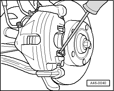
–  Fit outer brake pad onto brake carrier.
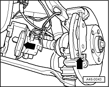
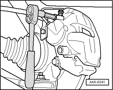
–  Screw the brake caliper to the brake support plate with the two guide pins, tightening them to 25 Nm.
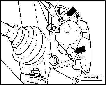
–  Fit the two protective covers.
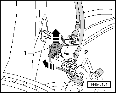
–  Insert retaining spring into brake calliper housing.
–  Connect brake pad wear indicator connector.
–  Mount the wheels → Running gear, shafts, steering; Rep. gr.44
  Note
t  Insert the retainer spring under the brake carrier once it has been inserted into the two holes. If this is incorrectly fitted then the wear on the outer pad cannot be corrected, this will gradually extend the pedal stroke.
t  After fitting the brake pads, operate the brake pedal strongly with the vehicle stopped so that the brake pads adopt the position corresponding to normal operation.
–  Check the brake fluid level and refill in case of doubt.
  A46-0043

Heat protection plate for the front brake disc FN3: Removing and installing > < Front brake callipers FN3: Removing and installing