Leon Mk1
| Drive shaft with → tripod type joint AAR2600i - Assembly overview |
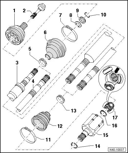
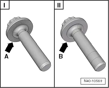
| 1 - | Outer constant velocity joint |
| q | Always replace completely |
| q | Removing → Fig. |
| q | Installation: insert onto the complete half-shaft by tapping with a plastic mallet, until the securing ring is decompressed |
| q | check → Chapter |
| 2 - | Bolt. |
| q | Different versions available |
| q | Assignment → Electronic parts catalogue „ETKA“ |
| q | Hexagon bolt = 200 Nm + 180° further |
| q | Loosening and tightening the hex bolt → Chapter |
 WARNING
|
| q | Replace after each removal |
| 3 - | Right hand driveshaft |
| 4 - | Left hand driveshaft |
| 5 - | Clamp |
| q | Replace after each removal |
| q | Tension → Fig. |
| 6 - | Dustguard for constant velocity joint |
| q | Ensure that there is no damage or cracks from friction |
| q | Material: → Hytrel (polyester elastomer) → Spare parts catalogue |
| 7 - | Clamp |
| q | Replace after each removal |
| q | Tension → Fig. |
| 8 - | Dished spring |
| q | Installation position → Fig. |
| 9 - | Thrust washer |
| q | Installation position → Fig. |
| 10 - | Circlip |
| q | Replace after each removal |
| q | Fit into the groove on the complete half-shaft |
| 11 - | Clamp |
| q | Replace after each removal |
| q | Tension using the pliers for spring-type clips -V.A.G 1275- |
| 12 - | Boot for triple roller joint |
| q | Ensure that there is no damage or cracks from friction |
| 13 - | Clamp |
| q | Replace after each removal |
| q | Tension using the pliers for spring-type clips -V.A.G 1275- |
| 14 - | Circlip |
| q | Replace after each removal |
| 15 - | Joint body |
| 16 - | Circlip |
| q | Replace after each removal |
| q | Insert into the driveshaft groove using the pliers -VW 161 A- |
| 17 - | Triple roller star with rollers |
| The chamfer -arrow- points towards drive shaft splines. |