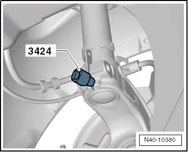
seat Workshop Repair Guides

SEAT Workshop Service and Repair Manuals

Removing and installing suspension strut > < Wheel suspension: assembly overview
Removal:
Removal:
  Note
Do not move the vehicle, if the propeller shaft is removed or completely removed from the wheel hub. If the vehicle must be moved, install an external joint first instead of a propeller shaft and tighten at 50 Nm.
  WARNING
The vehicle must be secured to the lifting platform, else the it could slip.
   
–  Secure the vehicle with support tool -T10038 - on both sides of the lifting platform.
–  Loosen the twelve-sided nut of the half-shaft → Chapter.
  Caution
The vehicle must not be resting on its wheels.
The wheel bearing can be damaged by the weight of the vehicle if the bolt is loosened.
–  Remove wheel → Chapter.
  N42-10114
–  Unscrew nut -arrow- and pull coupling rod -1- out from suspension strut.
–  Disengage the speed sensor wire from suspension strut.
  N40-10381
–  Remove clip for brake line -arrow- and unhook brake line at spring strut.
–  Pull connector off ABS speed sensor.
  N40-10371
–  Unscrew nuts -arrows-.
  Note
During disassembly and assembly work, take care that the rubber bellow of the ball joint is not damaged. Where necessary, protect the rubber bellow of the ball joint against damaged.
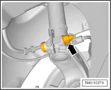
–  Remove the steering knuckle together with the traverse swinging arm ball joint.
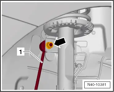
–  Remove the outer constant-velocity joint of the propeller shaft from the wheel hub. Use extractor -T20001A -, if necessary.
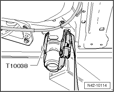
–  Tie the half shaft to the chassis using a wire.
  Caution
The drive shaft must not hang down. Otherwise, the interior articulation will be damaged by excessive bending.
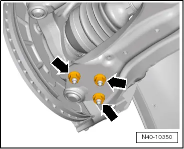
–  Rebolt the ball joint to the traverse swinging arm.
–  Remove the hydraulic jack -V.A.G 1383 A- from below the wheel hub.
  WARNING
t  Do not raise or lower vehicle while engine and gearbox jack -V.A.G 1383 A- is positioned under the vehicle. The vehicle could slip of the platform.
t  Do not leave engine and gearbox jack -V.A.G 1383 A- under vehicle for longer than necessary.
  N40-10350
–  Separate the threaded steering knuckle/suspension strut union -arrow-.
  N40-10379
–  Fit Separator device -3424- in the steering knuckle groove.
–  Turn the wrench 90° and remove it from the Separator device -3424-.
–  Push the brake disc down by hand towards the suspension strut.
  Note
Otherwise the shock absorber tube can cant in the bore of the wheel bearing housing.
–  Remove the steering knuckle from the shock absorber tube pulling downwards using the motordriven lift - V.A.G 1383 A- until the shock absorber tube is freed.
–  Tie wheel bearing housing to subframe with wire.
–  Remove the motordriven lift -V.A.G 1383 A- from below the steering knuckle.
  WARNING
Do not leave engine and gearbox jack -V.A.G 1383 A- under vehicle for longer than necessary.
–  Remove the rain guard duct → Bodywork, exterior fitting work; Rep. gr. 50 .
  N40-10380
–  Remove the hexagonal nut which secures the top end of the shock absorber.
1  - Commercially available ratchet
2  - -T10001/8-
3  - -T10001/11-
4  - -T10001/5-
–  Extract the telescopic arm.
  N40-10368

Removing and installing suspension strut > < Wheel suspension: assembly overview