seat Workshop Repair Guides

SEAT Workshop Service and Repair Manuals

Repair the rear axle (vehicles with brake disc) > < Trapezium link
Removing and installing trapezium link
Consult the equivalence table for tools and equipment according to applicability between Seat / VW / Audi / Skoda → Chapter.
Special tools and workshop equipment required
   
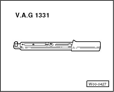
t  Torque wrench -V.A.G 1331-, see equivalent → Anchor.
  W00-0427
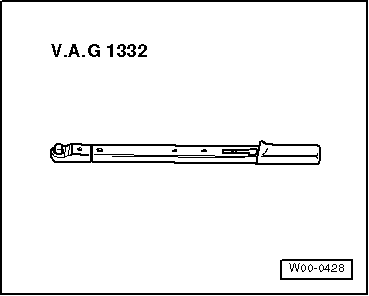
t  Torque wrench -V.A.G 1332-, see equivalent → Anchor.
Removal:
  Note
After repairs, check the wheel alignment → Chapter.
–  Remove underbody paneling from trapezoidal link → Body - outer assembly work; Rep. gr. 66 .
Vehicles with heavy-duty suspension
–  Remove stone deflector from trapezium link.
Continued for all vehicles
  W00-0428
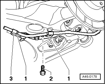
–  Attach the handbrake cable from the bracket under the trapezium link. For this purpose unscrew bolt -2-.
  A46-0178
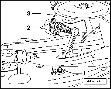
–  On vehicles with headlight range control, remove bolt -1-.
  A42-0243
–  Remove line guide on speed sensor. For this purpose remove bolts -1 and 2-.
–  Remove rear brake disk and heat shield → Brake system; Rep. gr.46 .
–  Remove coil spring → Chapter.
Remove right trapezoidal link.
  Note
Slightly lower subframe when unscrewing bolts for the right trapezoidal link on vehicles with front-wheel drive.
–  Remove bumper for wheel bearing housing. For this purpose unscrew bolted connection attaching it to the wheel bearing housing → Item
–  Lower subframe slightly → Chapter.
Both sides (continued):
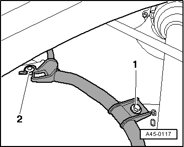
  A45-0117
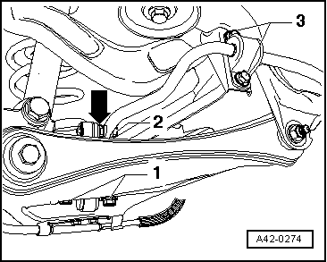
–  Unscrew lower mounting bolts -1- on stabiliser rod on trapezoidal link.
–  Unscrew mounting bolt-2- on stabiliser rod. The counterhold joint -arrow-with an open-end spanner.
–  Remove rod from stabiliser.
–  Mark eccentric bolt on trapezoidal link → Item on subframe.
Loosen following bolted connections on trapezoidal link:
t  Three bolted connections → Item
t  Bolted joint → Item
–  Remove the four bolted connections from trapezoidal link.
–  Remove tie rod and trapezoidal link.
Installation
Installation is carried out in the reverse sequence; note the following:
Renew screws and self-locking nuts ⇒ Instructions in the explosion illustrations overleaf → Chapter.
  Note
Bonded rubber bushes can only be turned to a limited extent. The mountings of the suspension links must therefore only be tightened when the suspension is in the unladen position → Chapter.
Install trapezoidal link and tie rod and manually tighten following bolted connections on trapezoidal link:
t  Three bolted connections → Item
t  Bolted joint → Item
  A42-0274
–  Install stabiliser rod and manually tighten mounting bolts -1- on stabiliser rod on trapezoidal link.
–  Manually tighten mounting bolt-2- on stabiliser rod. The counterhold joint -arrow-with an open-end spanner.
Install right trapezoidal link.
–  Install subframe → Chapter.
–  Install shock absorber on wheel bearing housing. For this purpose screw in bolted connection attaching it to the wheel bearing housing. → Item Tighten to specified tightening torque → Item
Both sides (continued):
  Note
Bonded rubber bushes can only be turned to a limited extent. The mountings of the suspension links must therefore only be tightened when the suspension is in the unladen position → Chapter.
Tighten bolts tightened manually to specified tightening torque. See values in following assembly surveys:
t  Tightening torque for the subframe: → Chapter
t  Tightening torque for trapezoidal link: → ChapterTighten eccentric bolt on trapezoidal link → Item and move to coincide with mark made during removal.
t  Tightening torque for the stabiliser rod: → Chapter
–  Install coil spring → Chapter.
–  Install brake disk and heat shield → Brake system; Rep. gr. 46.
–  Install line guide for speed sensor -2- → Brake system; Rep. gr. 45 .
–  Attach handbrake cable at bracket.
  A42-0274
–  On vehicles with headlamp range control, tighten bolt -1- to specified tightening torque → Item.
Vehicles with heavy-duty suspension
–  Install stone impact protection and tighten bolts to specified tightening torque → Item.
Continued for all vehicles
–  Install underbody paneling from trapezoidal link → Body - outer assembly work; Rep. gr. 66 .
–  Wheel alignment → Chapter
Setting of the running gear must be done with an alignment stand recommended by SEAT.
  A42-0243

Repair the rear axle (vehicles with brake disc) > < Trapezium link