| t
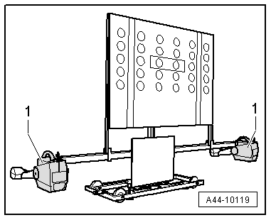
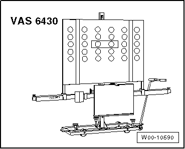
| Setting device -VAS 6430- |
| t
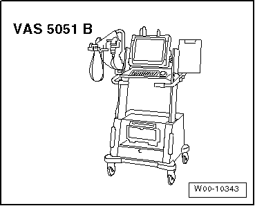
| Wheel alignment computer |

Note | t
| The driver assistance system's front camera -R242- must be correctly located in the holder. |
| t
| The field of view of the camera must be clean and clear. |
| t
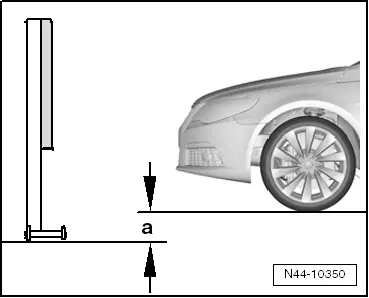
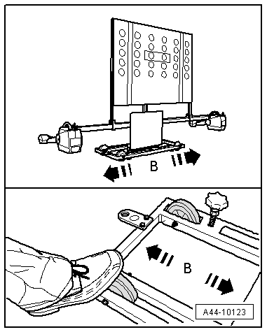
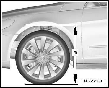
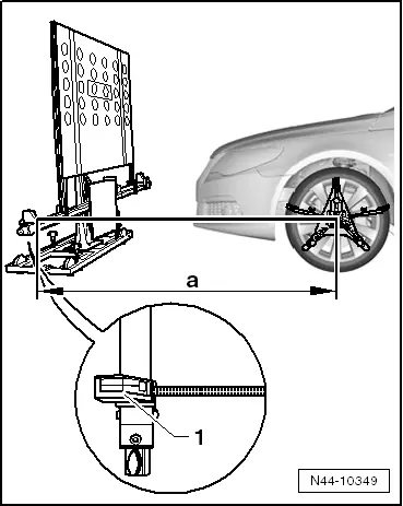
| Before driving the vehicle onto the wheel alignment platform, make sure there is sufficient space between the midpoint of the hub of the front wheels and the setting device -VAS 6430-. |
| t
| The distance between the setting device -VAS 6430- and the centre point of the hub of the front wheels must be 1,500 mm ± 25 mm. |
| t
| If the available space is not adequate, move the vehicle backwards on the alignment platform as required. |
| t
| Before calibrating, read out event memory and rectify faults as necessary. |
| –
| Note testing preconditions for wheel alignment → Chapter. |
| –
| Drive car onto wheel alignment platform. |
| –
| Connecting the Vehicle Diagnosis, Testing and Information System -VAS 505X - to the vehicle. (Route diagnostic cable through open window.) |
Note | During the calibration, make sure that all doors are closed on the vehicle and that the exterior lights are switched off. |
| –
| Bring wheels into straight-ahead position. |
| –
| Select calibration run for driver assistance system's -R242- front camera. |
| –
| Attach quick-release clamps to all four wheels. |
| –
| Mount measuring transducers on wheels. |
| –
| Carry out wheel rim run out compensation for rear wheels. |
|
|
|

 Caution