
Leon Mk1
| I - Assembly overview - subframe, anti-roll bar, lower wishbone up to model year 2000 |
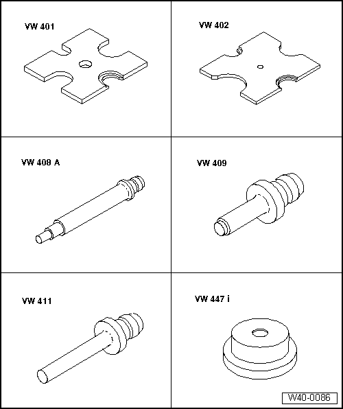
| Special tools and workshop equipment required |
| t | Press plate -VW 401- |
| t | Press plate -VW 402- |
| t | Press tool -VW 408 A- |
| t | Press tool -VW 409- |
| t | Press tool -VW 411- |
| t | Thrust plate -VW 447 i- |
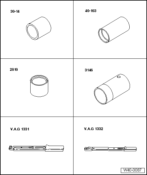
| t | Tube -30-14- |
| t | Support -40-103- |
| t | Tube -2010- |
| t | Tube -3146- |
| t | Torque wrench -V.A.G 1331- |
| t | Torque wrench -V.A.G 1332- |
 Note
Note| t | If a vehicle has to be moved after removing the drive shaft, first install outer joint and tighten to 50 Nm otherwise the wheel bearing will be damaged. |
| t | It is not permitted to carry out welding and straightening operations on load bearing suspension components or those components which locate the wheels. |
| t | Always renew self-locking nuts. |
| t | Always renew corroded nuts and bolts. |
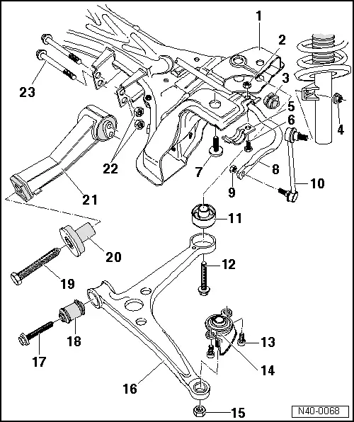
| 1 - | Subframe |
| After installing check position of steering wheel during a test drive. |
| If steering wheel is not in straight ahead position the front axle toe must be checked and if necessary adjusted! |
| 2 - | Hexagon nut |
| q | 55 Nm |
| 3 - | Rubber bush |
| 4 - | Nut |
| q | 100 Nm |
| q | Self-locking |
| q | Renew each time after removing. |
| 5 - | Clamp |
| 6 - | Hexagon bolt |
| 7 - | Hexagon bolt |
| q | M14 x 1.5 x 65 |
| q | 150 Nm and turn 90° further. |
| q | Renew each time after removing. |
| 8 - | Anti-roll bar |
| q | Removing and installing → Chapter. |
| 9 - | Nut |
| q | 100 Nm |
| q | Allocation → Electronic Parts Catalogue “ETKA”. |
| 10 - | Coupling rod |
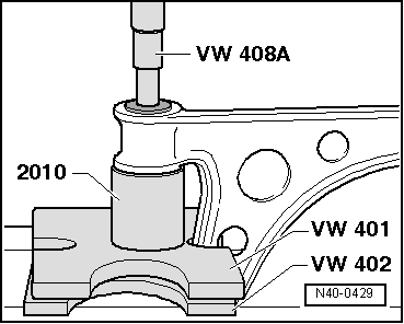
| 11 - | Rear wishbone mounting |
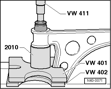
| q | Pressing out → Fig.. |
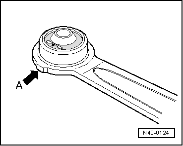
| q | Installation position → Fig.. |
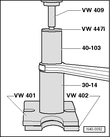
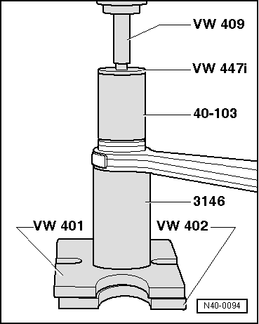
| q | Pressing in → Fig.. |
| 12 - | Hexagon bolt |
| q | M14 x 1.5 x 95 |
| q | 150 Nm and turn 90° further. |
| q | Check rear bonded rubber bush is correctly positioned in the subframe before tightening → Fig.. |
| q | Renew each time after removing. |
| 13 - | Allen head bolt, 55 Nm |
| 14 - | Swivel joint |
| q | Removing and installing → Chapter. |
| 15 - | Nut |
| q | 30 Nm and turn 90° further. |
| q | Self-locking |
| q | Renew each time after removing. |
| q | Brace with 7 mm Allen key while fitting the nut. |
| 16 - | Suspension link |
| q | Installation position in subframe → Fig. |
| q | Removing and installing → Chapter. |
| 17 - | Hexagon bolt |
| q | M14 x 1.5 x 90 |
| q | 90 Nm and turn 90° further. |
| q | Renew each time after removing. |
| 18 - | Front wishbone mounting |
| q | Pressing out → Fig.. |
| q | Pressing in → Fig.. |
| 19 - | Hexagon bolt |
| q | 60 Nm and turn 90° further |
| q | Always renew after removing |
| If the pendulum support, item → Item, is made of aluminium, the specified torque is 70 Nm. |
| Modifications to the screw → Chapter. |
| 20 - | Rubber bush |
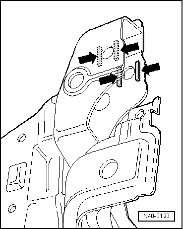
| 21 - | Pendulum support |
| At the start of production, supports with two and three holes for subframe mounting were produced. |
| After a short startup phase, these were replaced by a support with one hole. |
| Only the support with one hole will be supplied as a replacement part. |
| If this support is installed in a vehicle which was previously fitted with a different support, two spacers must be attached, each 2.5 mm thick. |
| Other modifications to the pendulum support → Chapter. |
| 22 - | Hexagon nut |
| q | Renew each time after removing. |
| 23 - | Hexagon bolt |
| q | 100 Nm |
| q | Always renew after removing |
|
|
Note
|
|
|
|
|
|
|
|
|
|