
Leon Mk1
| Repairing drive shaft, vehicles with manual gearbox 006 and automatic gearbox 099 |
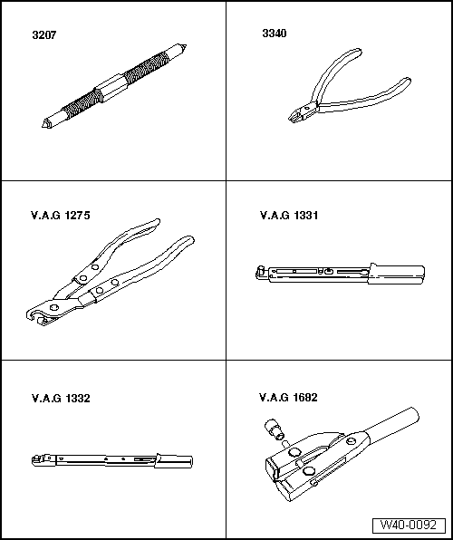
| Special tools and workshop equipment required |
| t | Spindle -3207- |
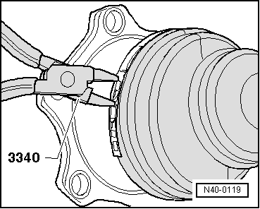
| t | Pliers -3340- |
| t | Pliers -V.A.G 1275- |
| t | Torque wrench -V.A.G 1331- |
| t | Torque wrench -V.A.G 1332- |
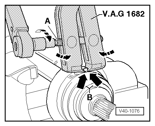
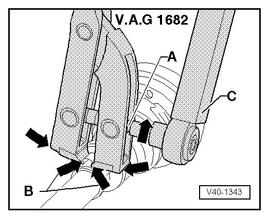
| t | Clamp tensioners -V.A.G 1682- |
|
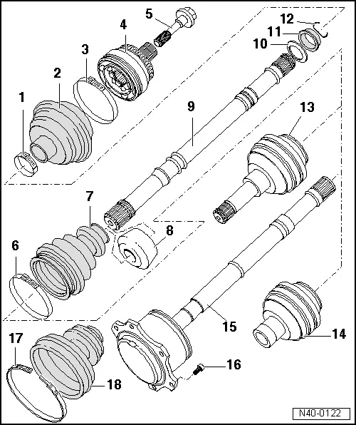
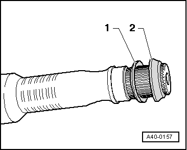
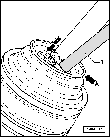
| 1 - | Clamp-type clip |
| q | Renew. |
| q | Tensioning → Fig.. |
| 2 - | Bellows for outer constant velocity joint |
| q | Check for tears and chafing, renew if necessary. |
| 3 - | Clamp-type clip |
| q | Renew. |
| q | Tensioning → Fig.. |
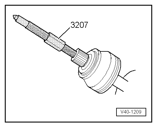
| 4 - | Outer constant velocity joint |
| q | Renew only complete. |
| q | Pressing off → Fig.. |
| q | Installing: drive onto shaft with plastic hammer until compressed circlip seats. |
| q | Greasing → . |
| q | Checking → Chapter. |
| 5 - | Hexagon bolt |
| q | 150 Nm and turn 90° further. |
| q | Renew each time after removing. |
| 6 - | Clamp-type clip |
| q | Renew. |
| q | Tension with -V.A.G 1275-. |
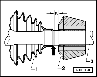
| 7 - | Bellows for inner constant velocity joint |
| q | Check for tears and chafing, renew if necessary. |
| q | Clean drive shaft thoroughly before installing new drive shaft bellows. |
| 8 - | Vibration damper |
| q | Installation position → Fig.. |
| 9 - | Drive shaft |
| 10 - | Dished washer |
| q | Installation position → Fig.. |
| 11 - | Thrust washer |
| q | Installation position → Fig.. |
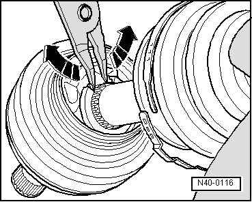
| 12 - | Circlip |
| q | Renew. |
| q | Remove and install with long nosed pliers. |
| 13 - | Left inner constant velocity joint |
| q | Renew only complete. |
| q | Driving off → Fig.. |
| q | Greasing → . |
| q | Checking → Chapter. |
| 14 - | Right inner constant velocity joint |
| q | Renew only complete. |
| q | Driving off → Fig.. |
| q | Greasing → . |
| q | Checking → Chapter. |
| 15 - | Drive shaft with outer joint (triple roller) |
| q | Vehicles with 4-cyl. engine and automatic gearbox. |
| q | Servicing inner joint is not possible. |
| q | Renew if damaged. |
| 16 - | Allen head bolt |
| q | Tighten using diagonal sequence to 10 Nm. |
| q | Tighten to 70 Nm. |
| q | Renew each time after removing. |
| 17 - | Clamp-type clip |
| q | Tensioning → Fig.. |
| 18 - | Bellows for inner constant velocity joint (triple roller) |
| q | Vehicles with 4-cyl. engine and automatic gearbox. |
| q | Remove outer constant velocity joint if joint bellows is to be renewed. |
| q | Clean drive shaft thoroughly before installing new drive shaft bellows. |
|
|
 Note
Note
|
|
|
|
|
|
|
|
|
|
|
|