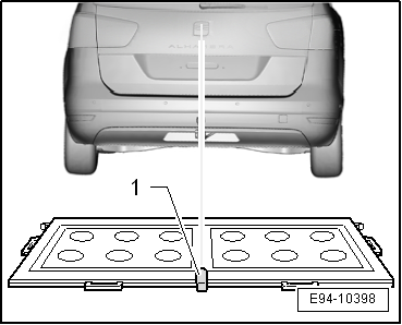
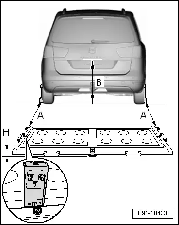
| If the distance measured on both sides of the calibration platform -VAS 6350/2-1- are identical with regard to the paddle -VAS 6350/1-2-, this results in -dimension A- (this must lie between 1,400 mm ÷ 1,900 mm) and must be entered in the vehicle diagnostic, testing and information system -VAS 505X- in „millimetres“. |

Note | Adjust the distance laser -VAS 6350/2- from the point that the measurement starts (front edge or rear edge) → Operating instructions. |
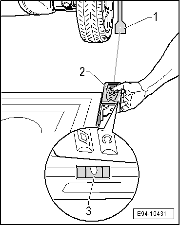
| –
| Position a ruler at the height of the reversing camera -R189- parallel to the ground, read off the dimension of the ruler on the ground using the distance laser -VAS 6350/2- (note the thickness of the ruler in the process). |
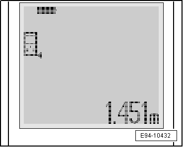
| The value obtained is -dimension B- (this must lie between 881 mm ÷ 924 mm) and must be entered in the vehicle diagnostic, testing and information system -VAS 505X- in „millimetres“. |
|
|
|