
Leon Mk2
| Gearbox electrical/electronic components |
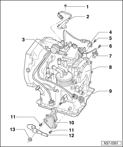
| 1 - | Bolt |
| q | 6 Nm |
| 2 - | Previous resistance -N207- |
| q | Location → Fig. |
| q | Checked by self-diagnosis → VAS 5051; Vehicle self-diagnosis |
| q | Uncouple the terminal connector → |
| q | Only in vehicles up to 06.00 |
| 3 - | Wiring harness |
| 4 - | Road speed sender -G68- |
| q | Location, removal and installation → Fig. |
| q | Checked by self-diagnosis → VAS 5051; Vehicle self-diagnosis |
| 5 - | Bolt |
| q | 6 Nm |
| 6 - | Bolt |
| q | 6 Nm |
| 7 - | Gearbox rev. speed sender -G38- |
| q | With connection cable |
| q | Location, removal and installation → Fig. |
| q | Checked by self-diagnosis → VAS 5051; Vehicle self-diagnosis |
| 8 - | Gearbox |
| 9 - | Wiring harness |
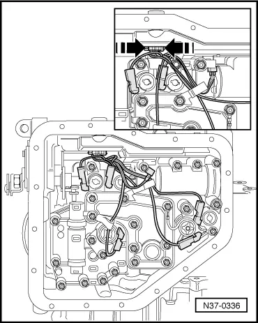
| q | For solenoid valves and gearbox oil temperature sender (ATF) -G93- |
| q | Location, removal and installation → Fig. |
| 10 - | Multi-function switch -F125- |
| q | Adjustment → Fig. |
| q | Checked by self-diagnosis → VAS 5051; Vehicle self-diagnosis |
| 11 - | Combi bolt |
| q | 3 Nm |
| 12 - | Rod |
| q | For the selector rod |
| 13 - | Nut |
| q | 17 Nm |
|
|