seat Workshop Repair Guides

SEAT Workshop Service and Repair Manuals

Input shaft: adjustment > < Input shaft - Installation overview
Disassembly and assembly of the input shaft
Check the tool and equipment equivalence table according to the applicability between Seat / VW / Audi / Skoda → Chapter.
   
Special tools and workshop equipment required
t  Pliers -A 81124-, see equivalent → Anchor
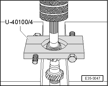
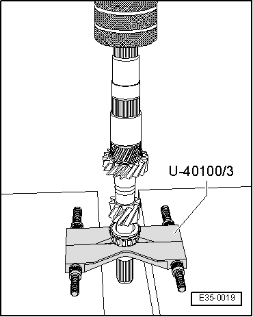
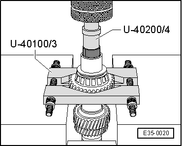
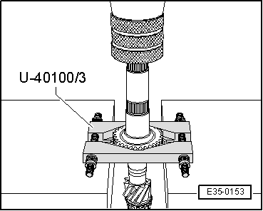
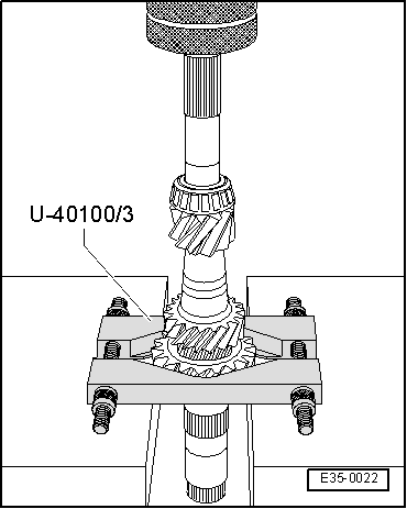
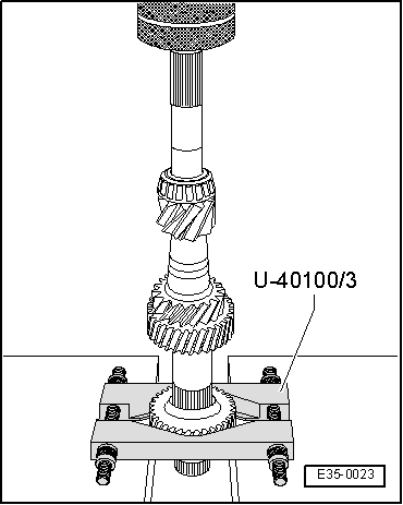
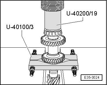
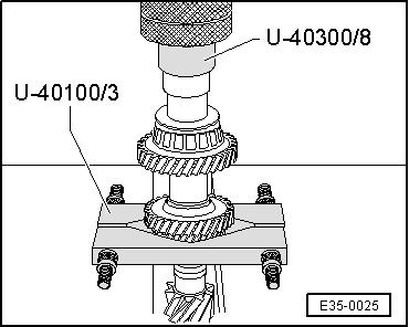
t  Extractor kit -U 40100B-, see equivalent → Anchor
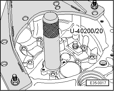
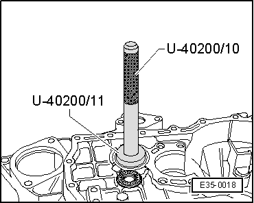
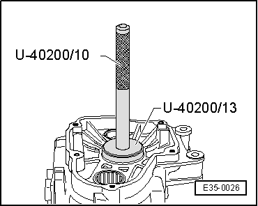
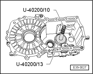
t  Kit (case) -U 40200A-, see equivalent → Anchor
t  Kit (case) -U 40300-, see equivalent → Anchor

   
Remove the outer track of the conical roller bearing
–  First remove guide bush → Chapter, Clutch release assembly: repairs.
  E35-0017
Install the outer track of the conical roller bearing
  E35-0018
Removing the roller bearing
  E35-0047
Install the roller bearing
  E35-0019
Remove the 4th gear mesh, roller bearing, thrust washer and bush for needle roller bearing.
–  Install flat base -U 40100/3- on the input shaft under the 4th gear mesh.
The gear of the 4thª gear is removed together with the conical roller bearing, the end washer and the needle bearing sleeve.
  E35-0020
Removing the 3rd gear mesh
–  Remove the securing ring with pliers -A 81124- before removing the 3rd gear mesh.
  E35-0153
Fitting the 3rd gear mesh
installation position
The gear collar must be facing the 4th gear mesh.
–  Fit the securing ring.
  E35-0022
Install 4th gear wheel
installation position
The gear collar should point toward the 4th gear wheel.
  E35-0023
Install the roller bearing
–  Install flat base -U 40100/3- below the 2nd gear mesh, and position adapter -U 40200/19- side A oriented towards roller bearing.
  E35-0024
Fit the attack washer and the bush for gear needle roller bearing
–  Install flat base -U 40100/3- below the 2nd gear mesh, and position adapter -U 40300/8- side B oriented towards roller bearing socket.
  E35-0025
Remove the outer track of the conical roller bearing
  E35-0026
Install the outer track of the conical roller bearing
  Note
If the input shaft has been adjusted, the shim must be fitted before assembling the outer track of the roller bearing
  E35-0027
Install synchromesh assembly of 5th gear
Install the 5th gear synchromesh unit as follows:
–  Place the sliding sleeve -2- on the synchromesh bush -3- so that the base strips align -A- in order to house the locking keys -4- of both components, and the teeth terminating in the end of the sliding sleeve are situated in the same direction as the most pronounced lug -B- of the locking keys.
–  Install the locking keys -4- and secure them with the springs -1- separating them 120º below the steps of the locking keys.
  N35-0017
Install springs in synchromesh assembly of 5th gear
–  Check that the teeth terminating in end -A- of the sliding sleeve are located in the same direction with the most pronounced lug -B- of the axle box.
–  Check that locking pins are correctly installed → Fig..
–  Position the springs separating them 120º, under steps -C- of the locking keys. The angled ends of the springs -arrows- must be outside the locking keys.
  V35-1320

Input shaft: adjustment > < Input shaft - Installation overview