seat Workshop Repair Guides

SEAT Workshop Service and Repair Manuals

Gearbox housing and clutch housing: repairs > < Removal:
Installing
Installing
–  Place the differential on the clutch housing.
   
–  Sealing washers -arrows- must always be renewed.
  Note
The figure only shows 3 or 4 bolts with their O-ring gaskets.
–  Place the input shaft, layshaft and reverse gear shaft together.
–  Partially diagonally screw in the 4 nuts on the secondary shaft bearing cover and then tighten to a torque of 25 Nm + 90°.
  Note
Clean remains of safety agent from the support thread for the reverse gear shaft. Use a tap.
–  Install the reverse gear shaft support
–  Fit the reverse gear fork.
  V34-2653
Installation position of reverse gear prong and shaft.
–  Fit the prongs with the connection guides.
  V34-2012
–  Screw stud bolt -A- M8×100 mm into support for reverse gear shaft so that it is aligned after attaching transmission housing.
–  Align the connection guides.
–  Check that the change-over bolts of the gearbox prongs are housed in their respective mobile sleeves.
–  Check that the magnet is not broken or cracked and place it in its housing in the clutch housing.
–  Thoroughly clean contact surfaces of clutch casing and gearbox casing. Apply a uniform layer (not too thick) of sealant paste → Spare parts catalogue.
–  Assemble the gearbox casing on the clutch housing.
–  Tighten screws securing the clutch housing to the gearbox casing to a torque of 25 Nm + 90°.
  V34-2008
–  Fit bolts for reverse gear shaft support -arrows- as shown:
–  Position bolt -a-, unscrew the M8 x 100 mm stud and tighten bolt -b- by hand
Tightening sequence:
1  - Bolt -a- 30 Nm (M8 x 32)
2  - Bolt -b- 25 Nm (M8 x 26)
  V34-2293
–  Install the bearing bolts -arrow- for the gearbox prongs. Use a screwdriver to align the connection guides, so that each support bolt can be installed in its housing.
–  Thoroughly clean contact surfaces of sealing cap for gear selector and casing. Apply a uniform layer (not too thick) of sealant paste → Spare parts catalogue.
–  Install the cover on the gear selector.
Install the gear selector shaft as follows:
–  Place the connection guides in neutral position.
  V34-2009
–  Locate lug -arrow 1- in recess in gearbox housing. Install the gear selector shaft so that connection finger -arrow 2- goes into to the engagement guides.
–  Screw in the fixing bolts of the gear selector lever in the gearbox housing and tighten these to 25 Nm.
  V34-2006
For vehicles with start stop system
–  Install the gearbox neutral position sender -G701--arrow- and tighten the screw to 5 Nm.
Continued for all vehicles
Installation position of 5th gear pinion:
  N34-11245
–  The lobe present -arrow- on the internal diameter of the gear must be orientated towards the gearbox casing.
–  Heat 5th gear pinion to approx. 100 ºC with the hot air blower -SAT 1416-.
  V34-2654
–  Press in sprocket with adapter -U 40200/20-.
  E34-0057
Check 5th gear synchrony ring for wear.
–  Before checking for wear, thoroughly clean the synchroniser ring and 5th gear mesh.
–  Fit 5th gear synchrony ring on the mobile pinion. Press the synchrony ring on the sprocket and measure the elevation „a“ with a thickness jig.
  V35-1125
Synchrony-ringMeasurement „a“ on
new
synchromesh
Wear limit
5. gear1,1 ... 1.7 mm0.5 mm

–  Fit the mobile 5th gear pinion with the needle bearing.
–  Fit 5th gear synchrony ring on the mobile pinion.
   
Install springs in synchromesh assembly of 5th gear
–  Install spring rings 120° offset below extensions -C-. Springs must seat with angled ends in front of locking pieces -arrows-.
–  Check that the teeth terminating in end -A- of the sliding sleeve are located in the same direction with the most pronounced lug -B- of the axle box.
–  Check that locking pins are correctly installed → Anchor.
  V35-1320
Installation position of the synchromesh unit / mobile sleeve of 5th gear
–  Install 5th gear wheel on input shaft so that the teeth on the conical selector sleeve -arrow 1- and the high collar on the synchromesh element -arrow 2- point toward the transmission housing.
–  Align recesses -arrow 3- on synchromesh hub to locking elements on synchromesh ring (-arrows- lower figure).
  N34-0059
5th gear synchromesh ring with connected locking elements -arrows-
–  Cover all holes with rag to prevent foreign body from penetrating into the transmission.
  N35-0018
–  Fit synchromesh assembly on 5th gear mobile pinion. Use the adaptorr - U 40200/20-.
  Note
When fitting synchromesh assembly to 5th gear, check the 5th gear synchromesh ring turns freely.
–  Clean bolt holes for mounting synchromesh element and 5th gear with tap to remove residues of bolt securing agent.
Otherwise the bolts may shear.
–  Partially screw mounting bolts → Item onto synchromesh element and 5th gear wheel.
Installation position of the plate spring
  E34-0058
–  The concave side of the plate springs -arrows- should point toward the synchronous hub and 5th gear wheel.
  V34-2658
Before tightening mounting bolts on synchromesh hub and 5th gear wheel, press 5th gear selector sleeve downward -arrow 1- and engage gear. Also shift into 1st gear with shift lever -arrow 2- and -arrow 3-.
The input and output shafts remain locked when two gears are engaged; the synchromesh hub and 5th gear wheel do not turn. Tighten the bolts -A- to a torque of 80 Nm.
–  Install 5th gear connection prong with a torque of 25Nm.
  N34-0927
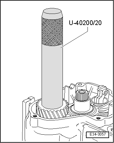
Adjust the sliding sleeve and the prong for the 5th gear
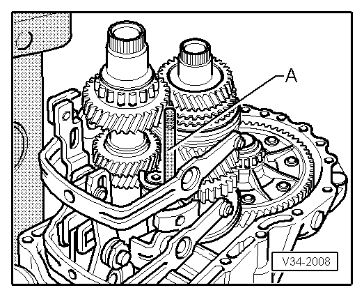
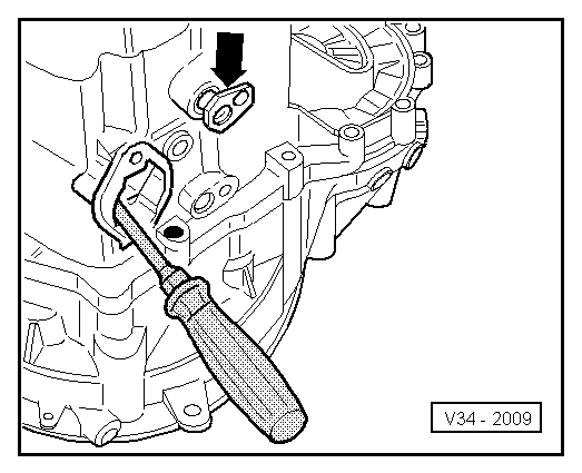
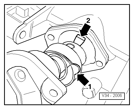
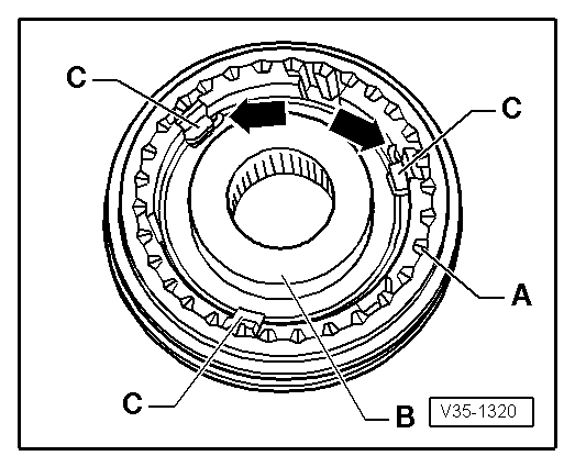
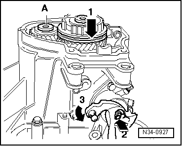
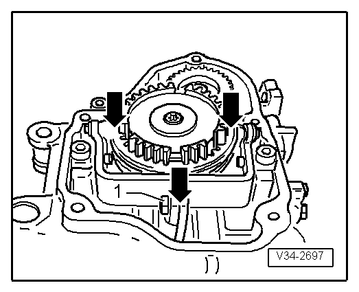
–  5. Gear engaged. Loosen bolt -1-. Press the mobile sleeve and the gear mouth in the direction of the -arrow-; then tighten the bolt -1- to 25 Nm.
l  
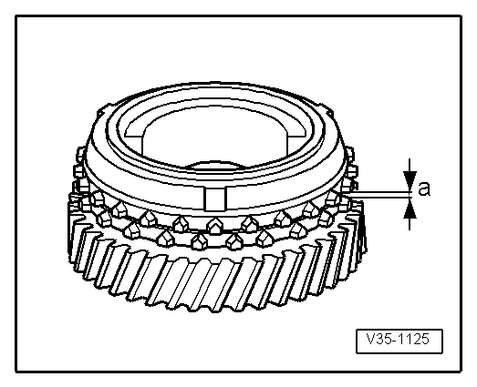
Control measurement: Between the mobile sleeve and the mobile pinion, a thickness gauge of 0.2 mm cannot be inserted. If necessary, repeat the adjustment process.
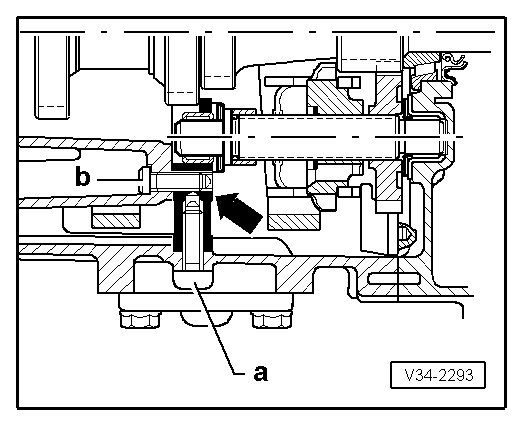
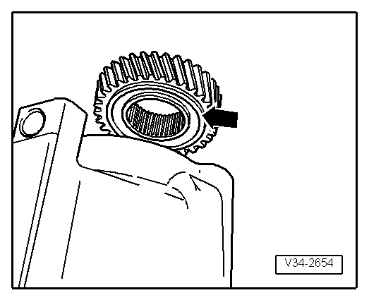
–  Shift out of 5th gear. The sleeve must be situated in neutral position and the synchrony ring must turn freely in this position.
–  Shift through all gears.
  V34-2697
–  Install the gasket and gearbox casing cover -arrow-.
–  Tighten the bolts to secure the gearbox casing cover to a torque of 10 Nm.
–  Fit guide socket for clutch release bearing and secure to casing using the three cylindrical bolts → Chapter
–  Install thrust washer, spring, conical ring and left articulation flange → Chapter.
  E34-10048

Gearbox housing and clutch housing: repairs > < Removal: