seat Workshop Repair Guides

SEAT Workshop Service and Repair Manuals

Gearbox housing and clutch housing > < Removal:
Installation
Installation
  Note
t  Insert the allotment with grooved ball bearings for the input and secondary shafts → Fig..
t  Pressing sleeve for 5th speed selector gear needle roller bearing onto input shaft → Fig..
   
If the 5th speed selector gear cannot be extracted.
–  Once assembled, fit the input shaft -2-, the secondary shaft -1- with the grooved ball bearing allotment on the pressure tool -T10080 -.
–  Insert selector mechanism (selector forks) -4- in the shaft locking collars.
–  Fit the reverse gear shaft -3- with the pinion.
–  Screw in the guide sleeve -T10079- on the reverse gear threaded attachment pin -arrow-.
  N34-10955
If the 5th speed selector gear can be extracted.
–  Position assembled components, input shaft -2- and output shaft -1- with bearing mounting for deep groove ball bearing, in thrust piece -T10080-.
–  Insert selector mechanism (selector forks) -4- in the shaft locking collars.
–  Fit the reverse gear shaft -3- with the pinion.
–  Screw in the guide sleeve -T10079- on the reverse gear threaded attachment pin -arrow-.
Continuation
  N34-1519
–  Put all of the components together in the gearbox casing inserting the guide pin -T10079 - through the hole where the gear operation mechanism is to fitted to the gearbox casing.
–  Unscrew the guide pin -T10079 -..
Note the following before pressing in:
t  Selector forks engage correctly in locking collars.
  A34-0303
t  The spacing -a- on the splines of output shaft.
  Note
t  Due to different spline heights, dimension -a-, output shafts of individual gearboxes have different lengths.
t  A shim -T10083/1- (3mm thick) may have to be fitted on the input shaft to ensure that the input shaft and the output shaft are always pressed in evenly.
t  This is the reason why dimension -a- for output shaft teeth must be measured.
  N34-11712
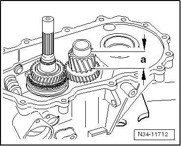
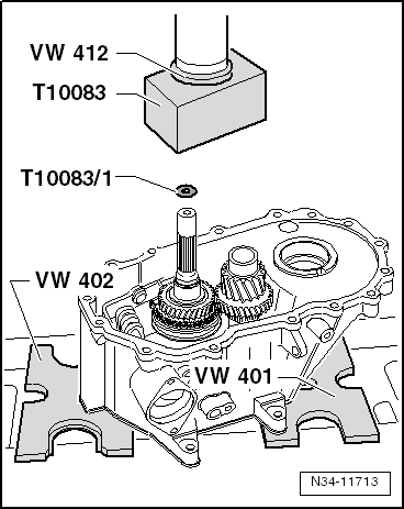
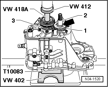
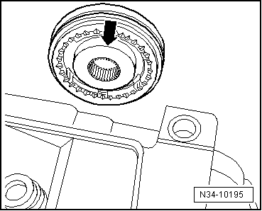
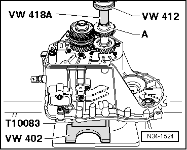
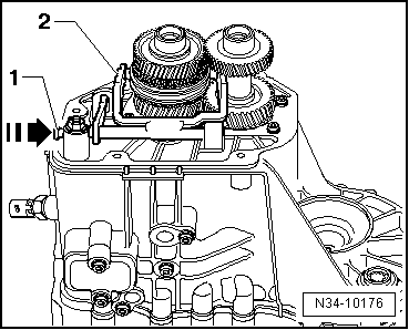
Dimension -a- = 30.6 mm
Place shim -T10083/1- onto input shaft ⇒ next figure.

   
Place shim -T10083/1- onto input shaft and carefully press in bearing mounting together with input shaft and output shaft to stop
  N34-11713
Carefully insert the allotment together with the input and secondary shafts to the end.
  A34-0304
–  Install bolt -A- for securing reverse gear wheel shaft.
–  Fit the bearing bush pins -B- in the lower part of the gearbox.
  A34-0300
–  Screw the reverse light switch -F4--C-.
–  Fit the bearing bush pins -B- in the upper part of the gearbox.
–  Set selector plates in neutral position.
–  Apply sealing paste -AMV 188 200 03- uniformly on the sealing surface of the selector shaft cover.
–  Install selector shaft with selector cover -A-. Then tighten bolts -arrows-.
For vehicles with start stop system
  N34-10170
–  Mount the gearbox neutral position sender -G701 - and tighten the screws -arrow- with the respective tightening torque → Item.
Continuation for all vehicles
  N34-11289
–  Tighten the input shaft and secondary shaft allotment with new bolts -A-.
  Note
Tighten the bolts to the corresponding torque, in steps and diagonally, beginning at the centre.
–  Tighten the hexagonal nut with collar -B- securing the gear operation mechanism (prongs).
–  Place the input and lay shafts together with the gearbox casing in the base for fitting - T10083 -.
–  Mount the 5th gear pinion -1- and the sleeve -2-.
  N34-10169
Installation position of 5th gear wheel
The high shoulder -arrow- faces gearbox housing cover.
If the 5th speed selector gear cannot be extracted.
–  Install gear wheel for 5th gear -1- and sleeve -2-.
  N34-1520
If the 5th speed selector gear can be extracted.
–  Pressing on gear wheel for 5th gear
–  Set sleeve on gear wheel for 5th gear item -2-.
Continuation
–  Fit the mobile 5th gear pinion -3- with the needle bearing.
–  Place 5th gear synchro-ring on synchromeshed gear.
  N34-10957
Installation position for mobile and 5th / 6th gear synchromesh
The highest collar -arrow- must face towards 5th gear and the gearbox casing.
–  Press on synchro-hub and locking collar for 5th and 6th gear → Fig..
  N34-10195
–  Heat the inner ring of the needle bearing of 6th gear to a maximum of 100°C and fit.
  WARNING
Wear protective gloves!
–  Install synchromeshed gear for 6th gear with needle bearing and synchro-ring.
  N34-1521
–  Fit the thrust ring -A- on top.
  Note
Do not interchange inner races of cylindrical roller bearings of input and output shafts.
–  Heat the roller bearing inner ring -B- to approx. 100 ºC, and fit it onto the input shaft.
  WARNING
Wear protective gloves!
  N34-1522
Installation position of 6th gear wheel:
The high collar should be facing the sleeve.
–  Set the locking collar -A- for 5th / 6th gear to neutral position to allow 6th speed selector gear to turn while pressing on 6th gear wheel.
–  Heat gear wheel for 6th gear to maximum 100° C.
  WARNING
Wear protective gloves!
–  Fit the gear pinion for 6th gear. Make sure that its teeth-B- and that of the mobile pinion -C- match.
  N34-1523
–  Heat the roller bearing inner ring -A- to approx. 100 ºC, and fit it onto the lay shaft.
  WARNING
Wear protective gloves!
  N34-1524
–  Next, place the oil collector -A- in the recess -1- and in the drill hole -2- of the gearbox casing.
  N34-10175
–  Mount the oil guide -B- on the gearbox casing.
–  Place the magnet on the oil guide -B-.
  N34-10171
–  Install differential -A-.
–  Apply an even coat of sealant paste -AMV 188 200 03- on the sealing surface.
–  Secure clutch housing to gearbox housing.
–  Rotate the gearbox on the assembly stand so that the gearbox casing is facing upwards.
  N34-10172
–  Before tightening the fastening bolts -A- 2 gears should be engaged -arrow 1- to -arrow 3-.
  N34-10203
–  Insert the 5th / 6th gear selector fork -2- and slide the pivot pin -1- in onto stop in direction of -arrow-.
–  Apply an even coat of sealant paste -AMV 188 200 03- on the sealing surface.
–  Tighten screws to secure the gearbox casing cover.
  N34-10176
–  Install both flange shafts with springs, thrust washers and tapered rings.
–  Fit the clutch release lever with clutch release collar and guide sleeve .
  V34-2737

Gearbox housing and clutch housing > < Removal: