
Leon Mk2
| Assembly overview - input shaft |
 Note
Note| t | Whenever new pinions or a new input shaft are fitted, please consult the technical data and the → Electronic catalogue of spare parts„ETKA“. |
| t | Install all bearings, synchromeshed gears and synchro-rings on input shaft with gear oil. |
| t | Do not mix up synchromesh rings. If re-using, allocate them to corresponding mobile pinion. |
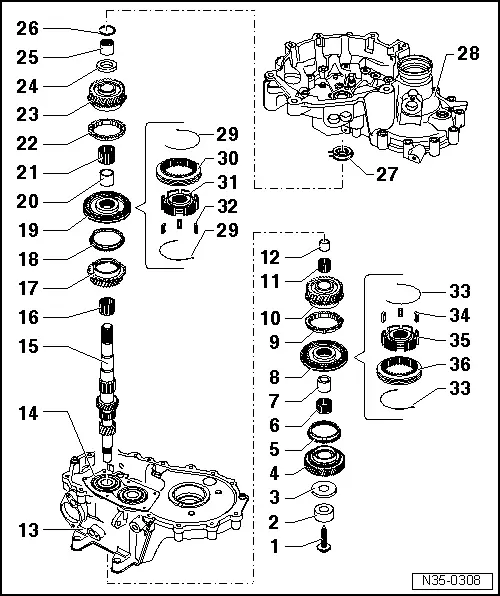
| 1 - | Bolt. |
| q | removing and fitting → Chapter |
| 2 - | Inner race of the cylindrical roller bearing |
| q | Mark before removal |
| q | Do not confuse with the inner ring of the layshaft roller bearing socket |
| q | These may be replaced individually |
| q | removing and fitting → Chapter |
| 3 - | Thrust washer |
| 4 - | Mobile pinion of 6th gear |
| 5 - | 6th gear synchro-ring |
| q | Check for wear → Fig. |
| 6 - | Needle bearing |
| q | For 6th gear |
| q | Replace along with → Item |
| 7 - | Thrust piece |
| q | For 6th gear needle bearing. |
| q | Replace along with → Item |
| q | removing and fitting → Chapter |
| 8 - | Locking collar with synchronising hub for 5th and 6th gear |
| q | Removing → Chapter |
| q | Fitting → Chapter |
| q | Dismantling → Fig. |
| q | Insert the unit comprising locking collar and synchromesh body of 5th / 6th gear → Fig. and → Fig.. |
| q | Installation position → Fig. |
| 9 - | Synchromesh ring of 5th gear: |
| q | This will be damaged when the input shaft is removed |
| q | Always replace. |
| q | Check for wear → Fig. |
| 10 - | 5th speed selector gear |
| 11 - | Needle bearing |
| q | for 5th gear |
| q | Replace along with → Item |
| 12 - | Thrust piece |
| q | For 5th gear needle bearing |
| q | Replace along with → Item |
| q | Press off with bearing mounting with deep groove ball bearing → Fig. |
| q | Pressing in → Fig. |
| 13 - | Gearbox |
| q | Repairing → Chapter |
| 14 - | bearing mounting with grooved ball bearing |
| q | Always replace the bearings with the allotment |
| q | Replace the allotment whenever it detaches from the gearbox casing |
| q | Pressing off → Fig. |
| q | Pressing in → Fig. |
| 15 - | Input shaft: |
| q | Clean any traces of fixing agent from the threaded holes in the input shaft using a tap. |
| 16 - | Needle bearing |
| q | for 3rd gear |
| 17 - | Synchromeshed gear for 3rd gear |
| 18 - | Synchromesh ring of 3rd gear |
| q | Check for wear → Fig. |
| 19 - | Locking collar with synchro-hub for 3rd and 4th gears |
| q | Press off with 3rd gear synchromeshed gear → Fig. |
| q | Dismantling → Fig. |
| q | Installation position, locking collar and synchro-hub → Fig. |
| q | Assembling → Fig. |
| q | Pressing in → Fig. |
| 20 - | Thrust piece |
| q | For needle bearing for the 4th gear |
| q | Replace along with → Item |
| q | Press off with 3rd gear synchromeshed gear → Fig. |
| q | Pressing in → Fig. |
| 21 - | Needle bearing |
| q | for 4th gear |
| q | Replace along with → Item |
| 22 - | Syncromesh ring for 4th gear |
| q | Check for wear → Fig. |
| 23 - | Synchromeshed gear for 4th gear |
| 24 - | Thrust washer |
| 25 - | Inner race of the cylindrical roller bearing |
| q | Pressing off → Fig. |
| q | Pressing in → Fig. |
| 26 - | Circlip |
| q | replace |
| q | Determining thickness → Fig. |
| 27 - | Cylindrical roller bearing |
| q | With retaining ring |
| q | Remove → Fig. |
| q | Pressing in → Fig. |
| q | Installation position: the securing ring of the bearing must point to the input shaft |
| 28 - | clutch housing |
| q | Repairing → Chapter |
| 29 - | Spring |
| q | Installation position → Fig. |
| 30 - | Locking collar for 3rd and 4th gear |
| 31 - | Synchromesh body of 3rd and 4th gear |
| 32 - | Locking pieces (3 off) |
| 33 - | Spring |
| q | Installation position → Fig. |
| 34 - | Locking pieces (3 off) |
| 35 - | Synchronising hub for 5th and 6th gear |
| 36 - | Locking collar for 5th and 6th gear |