seat Workshop Repair Guides

SEAT Workshop Service and Repair Manuals

Clutch pedal switchF36 : Removing and installing > < Check the function of the clutch master cylinder
Remove and install bearing bracket and master cylinder
Observe the notes on removing and installing clutch master cylinder → Chapter
Check the tool and equipment equivalence table according to the applicability between Seat / VW / Audi / Skoda → Chapter
Special tools and workshop equipment required
   
t  Hose clamps -3094-, see equivalent → Anchor
  W00-0079
t  Pliers -V.A.G 1922-
Removal:
  Caution
Follow steps required when disconnecting battery → Electrical system; Rep. gr. 27.
–  With the ignition switched off, disconnect battery earth strap → Electrical system; Rep. gr. 27.
  W00-1100
–  Use screwdriver to pry off the two caps -3-.
–  Unscrew nuts -4- and detach the two wiper arms -2-.
–  Pull off clips -1- and detach cowl panel grille -5-.
  A20-0833
Take the electronics box out of the plenum chamber as follows:
–  Unscrew bolts -arrows- and take off the cover.
  A10-0996
–  Use screwdriver to carefully pry off retaining strap -arrow-.
–  Lay aside engine control unit with connectors attached.
  A10-0997
–  Unplug connectors -2- at connector console.
–  Unscrew electrical line connector -1-.
  A10-1000
–  Release retaining clips -arrows- and lift auxiliary relay carrier out of electronics box.
–  Remove engine wiring harness together with rubber grommet from cutout in electronics box.
  A10-1001
–  Remove nuts -arrows- and lift out electronics box -1-.
  Note
t  In the following steps make sure that no brake fluid escapes into the plenum chamber or onto the gearbox below. If this does happen, clean the affected area thoroughly.
t  When performing work in the footwell, put cloths on the carpet to protect it from possible brake fluid spills.
  A30-0083
–  Clamp supply hose -A- from brake fluid reservoir using hose clamp -3094-. Pull hose off master cylinder and plug hose.
–  Remove rubber grommet from bulkhead above connection pipe for supply hose.
–  Lever out retaining clip -C- using a screwdriver and pull out pipe/hose assembly -B- slightly.
  A30-0033
–  Unscrew bolt for brake fluid reservoir -1- and unplug connector for brake fluid level warning contact downwards.
  Note
The brake fluid reservoir does not have to be removed.
  A47-0140
–  Remove vacuum line from brake booster -1-.
–  Remove the two Torx bolts -arrows-.
  Note
t  The brake fluid reservoir is not shown in the figure for better illustration.
t  The brake fluid reservoir must be moved slightly to the side in order to unscrew the upper Torx bolt.
–  Remove storage compartment on driver's side → General body repairs, interior; Rep. gr. 68.
–  Remove over-centre spring → Chapter.
  A30-0082
–  Disconnect brake pedal from brake servo → Brake system; Rep. gr.47 .
  A47-0144
–  Disconnect steering column from steering box -arrow A- → Running gear, front-wheel drive and four-wheel drive; Rep. gr.48.
–  Unplug connectors from clutch pedal switch-1-, brake light switch-2- and accelerator pedal module -3-.
–  Unscrew securing bolt for mounting bracket -arrow B- and remove entire pedal cluster.
  A30-0084
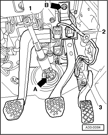
Release master cylinder operating rod from clutch pedal as follows:
  Note
t  
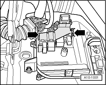
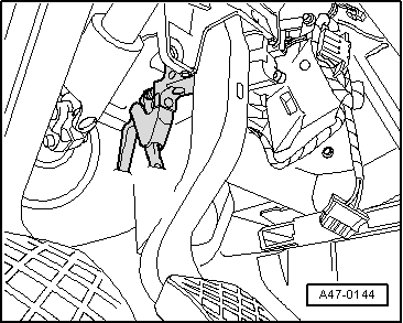
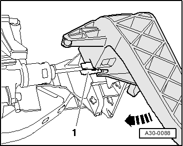
When releasing the operating rod, make sure that clutch pedal does not collide with mounting bracket for clutch pedal switch -arrow-. While doing this, the mount can break.
t  
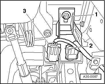
Install clutch pedal switch only once so that the clutch pedal switch -F 36- → Item is seated correctly in the pedal assembly.
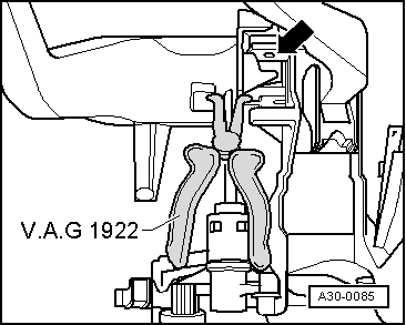
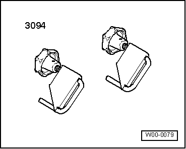
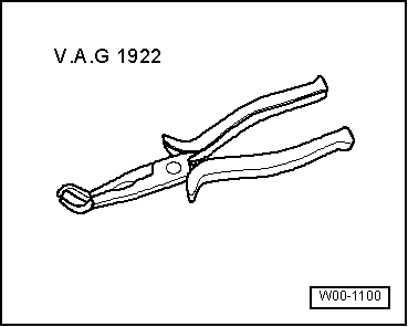
–  Apply spark plug connector pliers -V.A.G 1922- in clutch pedal recesses, press on sides of retaining clip → Item and detach clutch pedal from clutch master cylinder.
  A30-0085
–  Detach retaining clip -1- and remove clutch pedal -2-.
–  Unscrew bolts -3- and remove clutch master cylinder -4-.
Installation
Installation is carried out in reverse order, noting the following:
  A30-0086
–  Fit clutch master cylinder -4- and tighten bolts -3- to 20 Nm.
  A30-0086
–  Insert mount -1- in clutch pedal.
–  Lock clutch pedal in position by pressing in -direction of arrow-. Check whether mount -1- is seated correctly on the clutch pedal.
  A30-0088
The aid of a second mechanic is required for the following work.
–  Insert entire pedal cluster and tighten bolt -1- by hand. The second mechanic should guide pipe/hose assembly into clutch master cylinder from plenum chamber.
  A30-0087
–  Tighten bolts for brake servo -arrows- to 25 Nm.
  A30-0082
–  Push retaining clip -A- to stop.
–  Insert pipe/hose assembly -B- in clutch master cylinder and make sure that it engages audibly.
–  Fit rubber grommet -D- onto connecting pipe for supply hose -A- at bulkhead.
–  Push supply hose -A- from brake fluid reservoir on as far as it will go.
–  Remove hose clamp -3094-.
  A30-0055
–  Screw in securing bolt -1- for brake fluid reservoir and plug in connector at brake fluid level warning contact.
  A47-0140
–  Tighten hexagon socket head bolt -arrow B- for securing pedal cluster to dash panel carrier to 25 Nm.
–  Plug in connectors -1-, -2- and -3-.
–  Connect brake pedal to brake servo → Brake system; Rep. gr.47.
–  Secure steering column to steering box -arrow A- → Running gear, front-wheel drive and four-wheel drive; Rep. gr.48.
–  Install over-centre spring → .
–  Install storage compartment on driver's side → General body repairs, interior; Rep. gr. 68.
–  Bleeding clutch system → Chapter
  A30-0084
–  Insert electronics box and tighten nuts -arrows- to 4 Nm.
–  Route engine wiring harness and connect connector in connection station.
–  Install engine control unit → Engine, injection system; Rep. gr.23 or → Rep. gr.24.
–  If applicable, install auxiliary relay carrier and auxiliary fuse carrier → Electrical system; Rep. gr. 97.
–  Press on cap hand-tight and tighten bolts crosswise to 4 Nm.
  A30-0083
–  Fasten cowl vent grille -5- with clips -1-.
–  Install both wiper arms -2- and fasten with both nuts -4-.
–  Install both caps -3-.
–  Take all the necessary precautionary measures when connecting the battery → Electrical system; Rep. gr. 27.
  A20-0833

Clutch pedal switchF36 : Removing and installing > < Check the function of the clutch master cylinder