seat Workshop Repair Guides

SEAT Workshop Service and Repair Manuals

Determining the circlip in front of the input shaft ball bearing > < Circlips for input shaft ball bearing: determine
Determining thickness for circlip behind the input shaft ball bearing
   
–  Fit a provisional circlip -arrow- in the rear groove on the input shaft.
–  Then push ball bearing onto input shaft.
Installation position:
The sealed side of the ball cage faces the gearbox housing.
  V35-1238
–  Insert the ball bearing:
First screw pin (M8 and M10) -3114/2- into tapped hole for ball head stud.
Slide the thrust plate -T10246/2- onto input shaft.
Now position fitting tool -T10246/1- behind splines for clutch plate. Tighten bolts -A- only slightly. The bolts locate in the recesses in the thrust plate -T10246/2 -.
Press in ball bearing onto the stop by tightening the bolts alternately (1/2 turn at a time).
  A34-10123
–  Then fit dished spring -1-.
Installation position:
The convex side faces guide sleeve -2-.
–  Fit a shrink hose onto input shaft splines.
–  Bolt guide sleeve to gearbox housing -2- with bolts -3-.
–  Then turn the gearbox housing so the joint flange for the bearing housing points upwards.
l  The contact surface must be cleaned to remove sealing paste.
  A35-10024
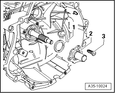
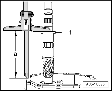
–  Place thrust washer -1- for 4th and 5th speed selector gears onto input shaft.
–  Place a digital depth gauge (e. g. -VAS 6087-) onto the thrust washer and measure the distance to the contact surface of the housing. The measuring point on the housing contact surface must be as close to the input shaft as possible.
  Note
When measuring, lift the input shaft with e.g. support bridge - 30-211A- or the help of a second mechanic until the play in the ball bearing is taken up.
Specification for dimension „a“: 164.14 mm
  Note
t  If the measured value exceeds the specification, use a thinner circlip than the circlip installed so that the specification is attained.
t  If the measured value is below the specification, use a thicker circlip than the circlip installed so that the specification is attained.
t  Determine the circlip thickness to meet the specification as exactly as possible (164.14 mm).
The following retaining rings are available:
  A35-10025
Retaining ring thickness (mm)
1,542,082,62
1,632,172,71
1,722,262,80
1,812,352,89
1,902,44 
1,992,53 

–  Determine circlip using table, part number → Spare parts catalogue
   
Checking adjustment and checking distance „a“
l  Determined circlip is installed.
The distance „a“ should be 164.14 mm ± 0.04 mm if the correct circlip has been selected.
  A35-10025

Determining the circlip in front of the input shaft ball bearing > < Circlips for input shaft ball bearing: determine